


12
Caution: The supplied AC Power Cord should not be
connected to the Rear Panel of the MC252 Amplifier
until after the Loudspeaker Connections have been
made and the supplied protective Terminal
Connection Covers have been installed. Failure to
observe this could result in Electric Shock.
There are two different ways of operating the MC252 mon-
aurally, Mono Bridged Mode and Mono Bi-Amp (Parallel)
Mode. The Mono Bridge Mode allows for Loudspeakers of
4S (ohm), 8S (ohm) or 16S (ohm) impedance to be con-
nected to the MC252. The Mono Bi-Amp (Parallel) Mode
allows for Loudspeakers of 1S (ohm), 2S (ohm) or 4S
(ohm) impedance to be connected to the MC252.
Choose the appropriate Mono Mode determined by the
impedance of your Loudspeakers. If the Mono Bridge
Mode is appropriate for the Loudspeakers, proceed to page
10 for proper connections.
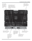
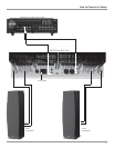
1. For Remote Power Control, connect a power control
cable from the Control Center or Preamplifier Power
Control Out to the MC252 Power Control In.
2. Connect cables from the Unbalanced Output of a McIn-
tosh Preamplifier or Control Center to the MC252
R/MONO Unbalanced Input.
Note: An optional hookup is to use balanced cables.
3. The MC252 Mono Bi-Amp (Parallel) Mode of Opera-
tion requires a Hookup Cable and jumper wires for con-
nection to the Power Amplifier Output Terminals; two
22 inch (55.88 cm) Jumper wires, and one Loudspeaker
Hookup Cable cut to the desired length. Prepare the
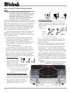
cable and wires by choosing one of the methods below:
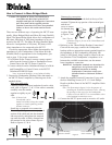
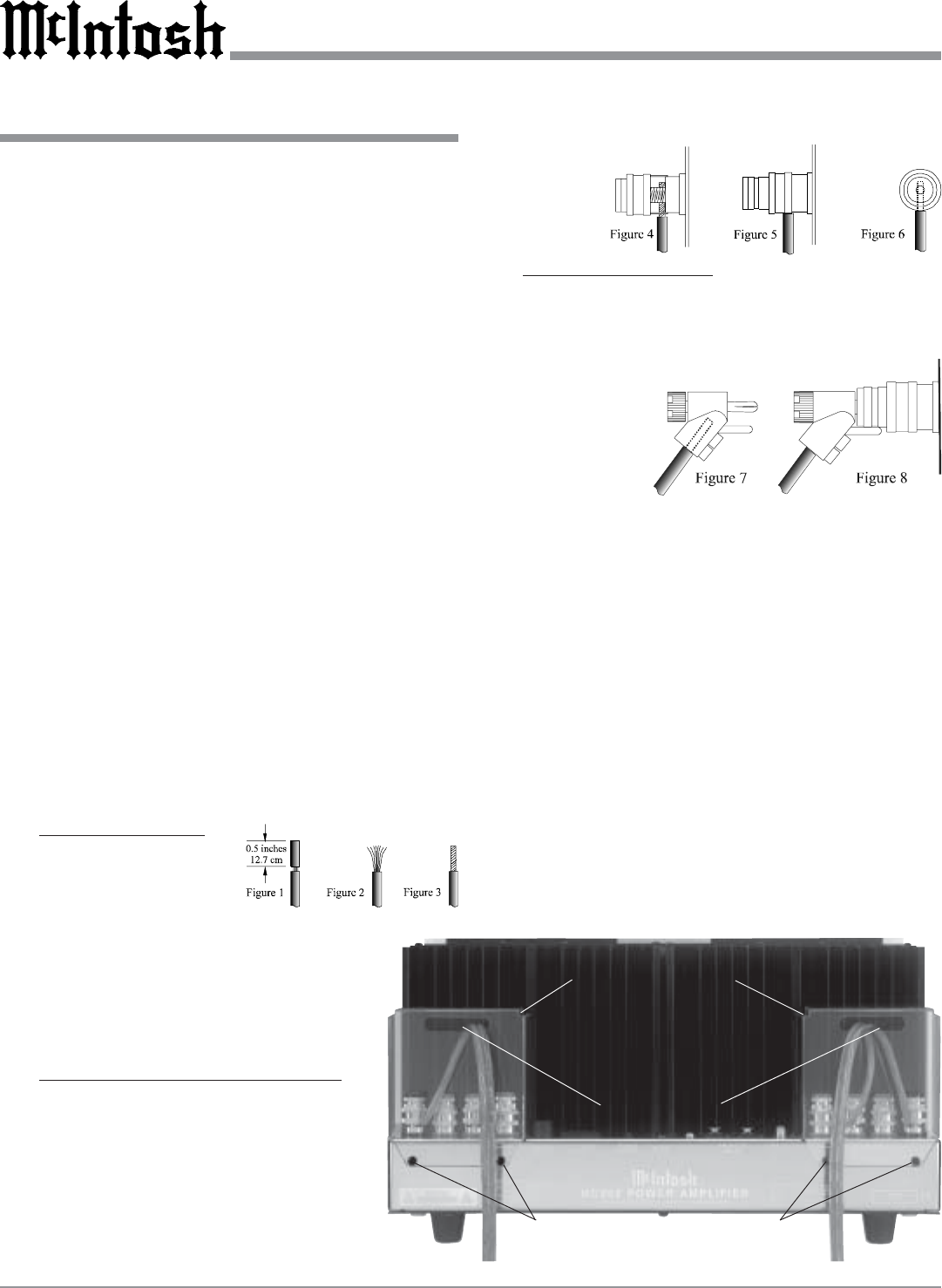
Bare wire cable ends:
Carefully remove suffi-
cient insulation from the
cable/wire ends, refer to
figures 1, 2 & 3. If the
cable/wire is stranded, carefully twist the
strands together as tightly as possible.
Note: If desired, the twisted ends can be tinned
with solder to keep the strands together,
or attach spade lug and/or banana
connector.
Spade lug or prepared wire connection:
Insert the spade lug connector or prepared
section of the cable/wire end into the termi-
nal side access hole, and tighten the termi-
nal cap until the cable/wire is firmly
clamped into the terminal so they cannot
slip out. Refer to figures 4, 5 & 6.
Banana plug connection:
Insert the banana plug into the hole at the top of the
terminal. Tighten the top portion of the terminal post
and the set screw to secure the banana plug in place.
Refer to figures
7 and 8.
Note: The use
of
Banana
Plugs is
for use in
the
United States and Canada only.
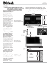
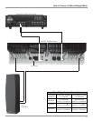
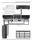
4. Refer to the “Mono Bi-Amp (Parallel) Hookup Con-
nections” Chart on the next page for making the fol-
lowing connections.
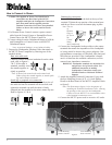
5. Insert the Loudspeaker Hookup Cable Ends through
the opening of both supplied Terminal Connection
Covers and connect the one of prepared Jumper Wire
between the two - Output Terminals and the other
Jumper Wire between the two appropriate Impedance
+ Output Terminals. Connect the Loudspeaker hookup
cable to appropriate output terminals based on the im-
pedance of the Loudspeaker (1S [ohm], 2S [ohm] or
4S [ohm]), being careful to observe the correct polari-
ties. If the Loudspeaker’s impedance is in-between the
available connections, use the nearest lower impedance
connection.
WARNING: Loudspeaker terminals are hazardous live
and present a risk of electric shock. For
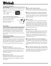
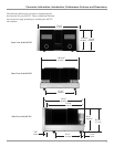
Terminal Connection Covers
Cover Mounting
Screw Locations
Cable Openings
Figure 9
Cover Mounting
Screw Location
How to Connect in Mono Bi-Amp (Parallel)
Mode