


17
Technical Description
rent gain over the entire current range they must cover.
Output transistors in particular, have matched uniform cur-
rent gain, high current-bandwidth product and large active
region safe operating area. An automatic tracking bias sys-
tem completely eliminates any trace of crossover distor-
tion. Precision metal film resistors and low dielectric ab-
sorption film capacitors are used in all critical circuit loca-
tions.
The output signal of the circuit is coupled together in
the unique McIntosh MC252 Output Autoformer. It pro-
vides low distortion power transfer at frequencies from be-
low 20Hz to well beyond 20,000Hz with optimum imped-
ance points of two ohms, four ohms and eight ohms. The
unequaled expertise of McIntosh in the design and manu-
facturing of autoformers is legendary in the high fidelity
industry.
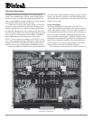
The high efficiency circuit design of the MC252 con-
tributes to low operating temperatures. More than 621
square inches of heat sink area keep the MC252 operating
safely with convection cooling. No fans are needed.
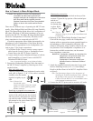
Autoformers
All solid state power amplifier output circuits work best
into what is called an optimum load. This optimum load
may vary considerably from what a loudspeaker requires.
In the case of more than one loudspeaker connected in par-
allel, the load to the power amplifier may drop to two ohms
or even less. A power amplifier connected to a load that is
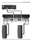
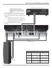
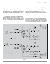
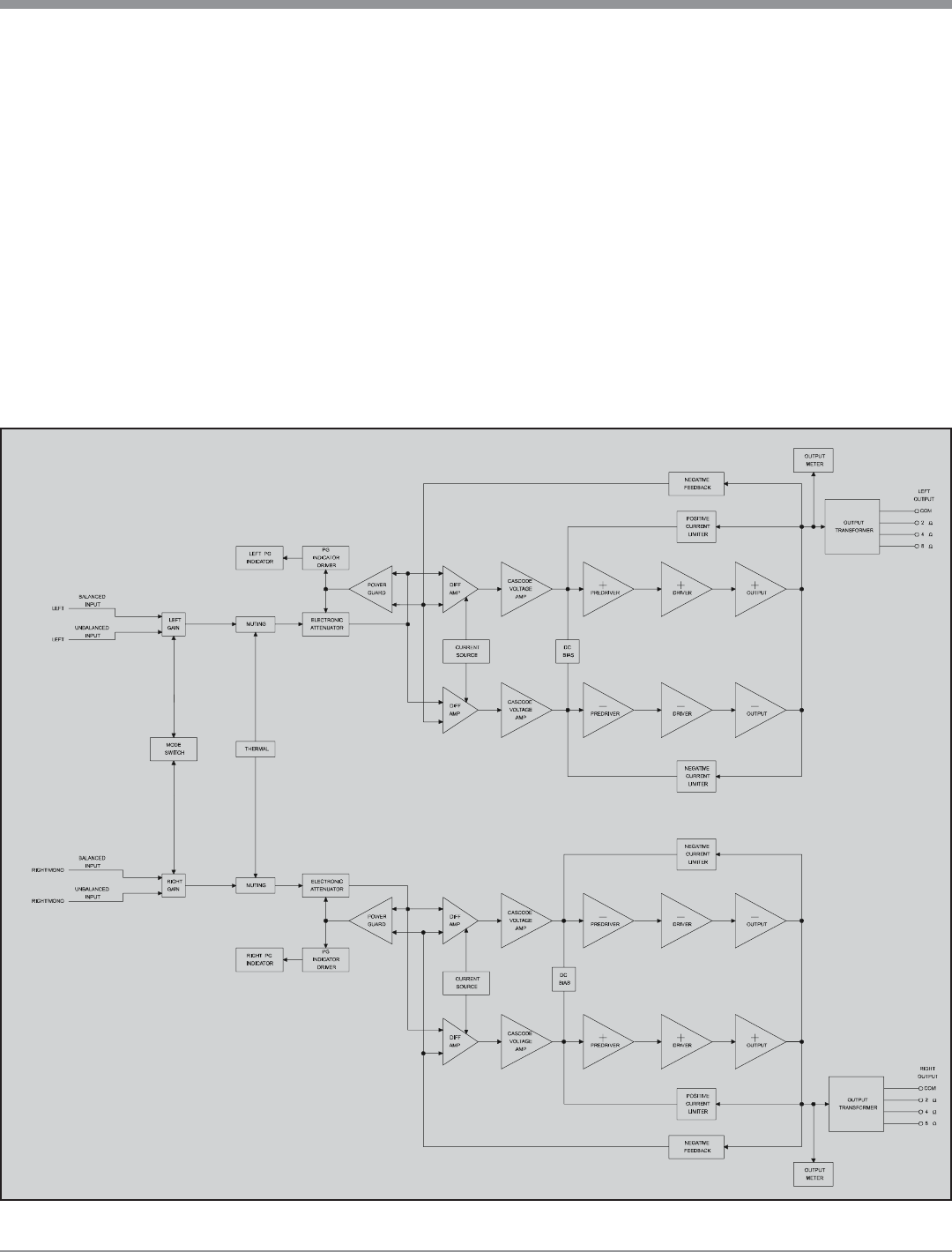
Figure 14
Block Diagram of the Amplifiers
and
Meter Circuitry