


8
terminals so the lugs
cannot slip out. Refer to
figures 4, 5 & 6.
4. Connect the loud-
speaker hookup ca-
ble to the output terminals that match the impedance of
your loudspeaker, being careful to observe the correct
polarities. Output impedance connections of 2 ohms,
4 ohms and 8 ohms are provided. If the impedance of
your loudspeaker is in-between the available connec-
tions, use the nearest lower impedance connection.
WARNING: Loudspeaker terminals are hazardous live
and present a risk of electric shock. For ad-
ditional instruction on making Loudspeaker
Connections contact your McIntosh Dealer
or McIntosh Technical Support.
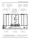
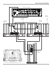
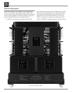
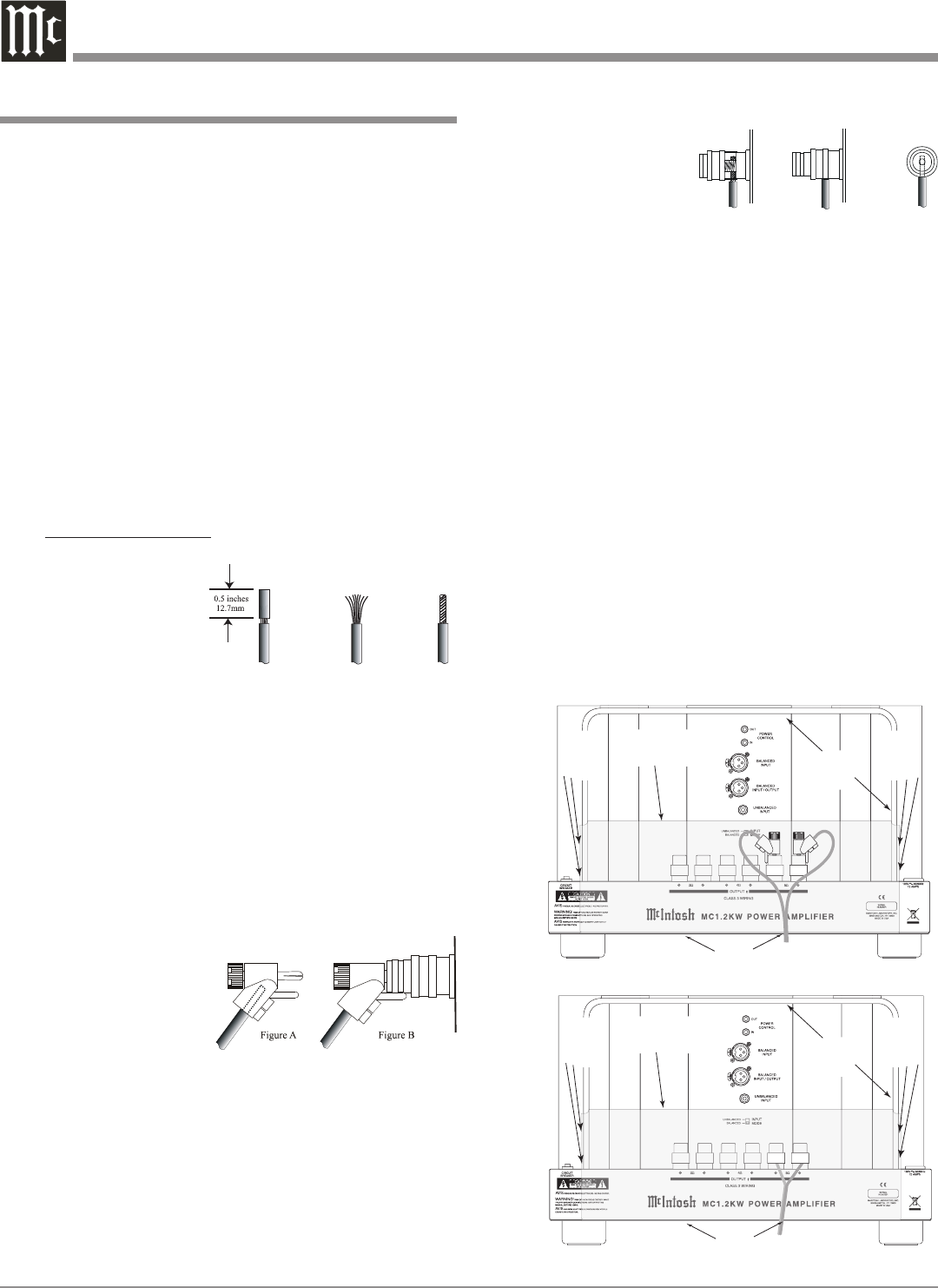
5. Attach the supplied Terminal Connections Cover with
the four Phillips Head Mounting Screws (10-32 x 1/2
inch) to the Rear Panel of the MC1.2KW Amplifier.
Refer to figures 7a and 7b.
Note: There are six openings on the bottom edge of the
cover to allow the Loudspeaker’s Cable to exit the
MC1.2KW. The Rear Chassis Handle has tapped
screw openings on both sides for securing the cover.
6. Connect the MC1.2KW power cord to an active AC
outlet.
Caution: The supplied AC Power Cord should not be con-
nected to the Rear Panel of the MC1.2KW Amplifier
until after the Loudspeaker Connections have been
made and the supplied protective Terminal Connec-
tions Cover has been installed. Failure to observe
this could result in Electric Shock.
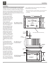
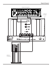
1. For Remote Power Control, connect a power control
cable from the Control Center or Preamplifier Power
Control Out to the MC1.2KW POWER CONTROL IN.
2. Connect a cable from the Balanced Output of a McIn-
tosh Preamplifier or Control Center to the MC1.2KW
BALANCED INPUT. Place the INPUT MODE Switch
in the BALANCED Position.
Note: An optional hookup is to use an unbalanced cable
and place the INPUT MODE Switch in the UNBAL-
ANCED Position.
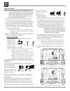
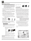
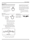
3. Prepare the Loudspeaker Hookup Cable for attachment
to the MC1.2KW Power Amplifier:
Bare wire cable ends:
Carefully remove sufficient insulation from the
cable ends, refer
to figures 1, 2 &
3. If the cable is
stranded, carefully
twist the strands
together as tightly as possible.
Notes: 1. If desired, the twisted ends can be tinned with
solder to keep the strands together.
2. Banana plugs are for use in the United States
and Canada only. In the United States, when us-
ing the 8 ohm loudspeaker terminals, it is man-
datory to use banana plugs inserted into the top
hole of the loudspeaker terminals in order to
comply with safety standard requirements.
Connection Method for use inside the United States and
Canada only:
Attach the previously prepared bare wire cable ends into
the banana plugs and
secure the connections.
Insert the banana plug
only into the hole at the
top of the terminal. Refer
to figures A and B.
Connection Method for use outside the United States
and Canada:
Attach the previously prepared bare wire cable ends into
the spade lug connectors and secure the connections.
Insert the spade lug connector or prepared section of the
cable end into the terminal side access hole, and tighten
the terminal cap until the cable is firmly clamped into the
How to Connect
Figure 1
Figure 2
Figure 3
Figure 4
Figure 5
Figure 6
Cable
Openings
Terminal
Connections
Cover
Cover
Mounting
Screw
Location
Cover
Mounting
Screw
Location
Rear
Chassis
Handle
Figure 7a (Inside USA and Canada)
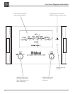
Cable
Openings
Terminal
Connections
Cover
Cover
Mounting
Screw
Location
Cover
Mounting
Screw
Location
Rear
Chassis
Handle
Figure 7b (Outside USA and Canada)