


16
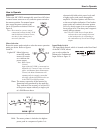
Autoformers
All solid state power amplifier output circuits work best
into what is called an optimum load. This optimum load
may vary considerably from what a loudspeaker requires.
In the case of more than one loudspeaker connected in
parallel, the load to the power amplifier may drop to two
ohms or even less. A power amplifier connected to a load
that is lower than optimum, causes more output current
to flow, which results in extra heat being generated in
the power output stage. This increase in temperature will
result in a reduced life expectancy for the amplifier.
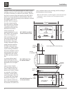
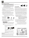
The special Balanced Dual Core Autoformer creates an
ideal match between the power amplifier output stage and
the loudspeaker. A McIntosh amplifier with an Autoformer
can be used to safely drive multiple speakers without
reducing the life expectancy of the power amplifier. Refer
to figure 14.
There is absolutely no performance limitation with an
Autoformer. Its frequency response exceeds that of the
output circuit itself, and extends well beyond the audible
range. Its distortion level is so low it is virtually impossible
to measure.
In the rare event of a power amplifier output circuit fail-
ure, the McIntosh Autoformer provides absolute protection
from possible damage to your valuable loudspeakers. The
unequaled expertise of McIntosh in the design and manu-
facturing of Autoformers is legendary in the high fidelity
industry. McIntosh engineers know how to do it right.
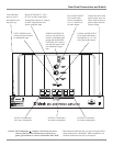
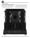
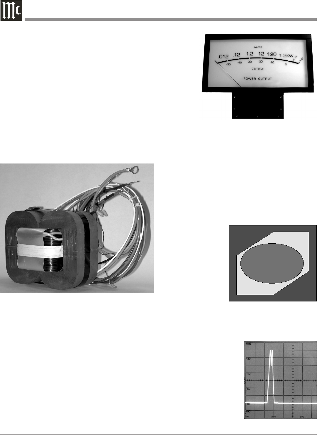
Power Output Meter
The McIntosh MC1.2KW has a huge hand built Output
Watt Meter that responds 95% full scale to a single cycle
tone burst at
2kHz. Refer
to figure
15. Voltage
and current
outputs are
electronical
-
ly measured,
multiplied
and fed to
a special
circuit that
accelerates
the pointer movement in the upward direction. When the
pointer reaches its peak it pauses only long enough for the
human eye to perceive its position, then drops. It is almost
10 times faster than a professional VU meter.
A front panel switch is provided to change the meter to
the Watts Hold Mode of operation. This allows fast upward
movement of the pointer but greatly increases Hold Time
at the peak of its travel. The highest power output of the
source material is thus recorded.
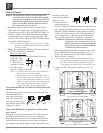
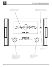
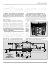
Protection Circuits
The MC1.2KW incorporates a version of the McIntosh
Sentry Monitor Output
Transistor Protection
Circuit. Refer to Fig
-
ure 16. There is abso-
lutely no compromise
in sonic performance
with this circuit, and it
ensures safe operation
of the amplifier under
even the most extreme
operating conditions.
The different types of
protection circuits incorporated in the MC1.2KW insure a
long and safe operating life. This is just one of the many
characteristics of McIntosh
Power Amplifiers that make
them world famous.
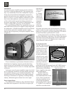
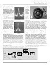
The MC1.2KW also
includes the unique pat-
ented McIntosh Power Guard
circuit. Power Guard elimi-
nates the possibility of ever
overdriving the amplifier
into clipping. Refer to figures
17, 18 and 19. An overdriven
amplifier can produce both
Figure 14
Figure 15
Figure 17
Input Test Signal
Figure 16
Normal Operating Area�
Sentry Monitor�
Safety Area
�
Output�
Transistor
�
Failure�