


15
Technical Description
cies is less than 0.002%. The true distortion readings
on the MC1.2KW are so low, it takes special measuring
techniques to make accurate readings. The MC1.2KW can
deliver the best possible performance from any type of
high quality loudspeaker system.
Creating an amplifier with this level of performance did
not come easily. Many months of design, testing and mea-
suring were required. Extensive controlled listening tests,
the ultimate form of measuring, were made before the final
design was accepted.
Design Philosophy
The design philosophy incorporated in the MC1.2KW
involved several different techniques, all based on sound
scientific logic. Every stage of voltage or current ampli
-
fication must be as linear as possible prior to the use of
negative feedback. McIntosh engineers know how to prop-
erly design negative feedback circuits so they contribute to
the extremely low distortion performance expected from
a McIntosh amplifier. The typical McIntosh owner would
never accept the approximately 100 times higher distortion
of many non-feedback designs.
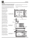
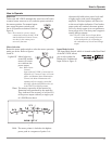
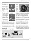
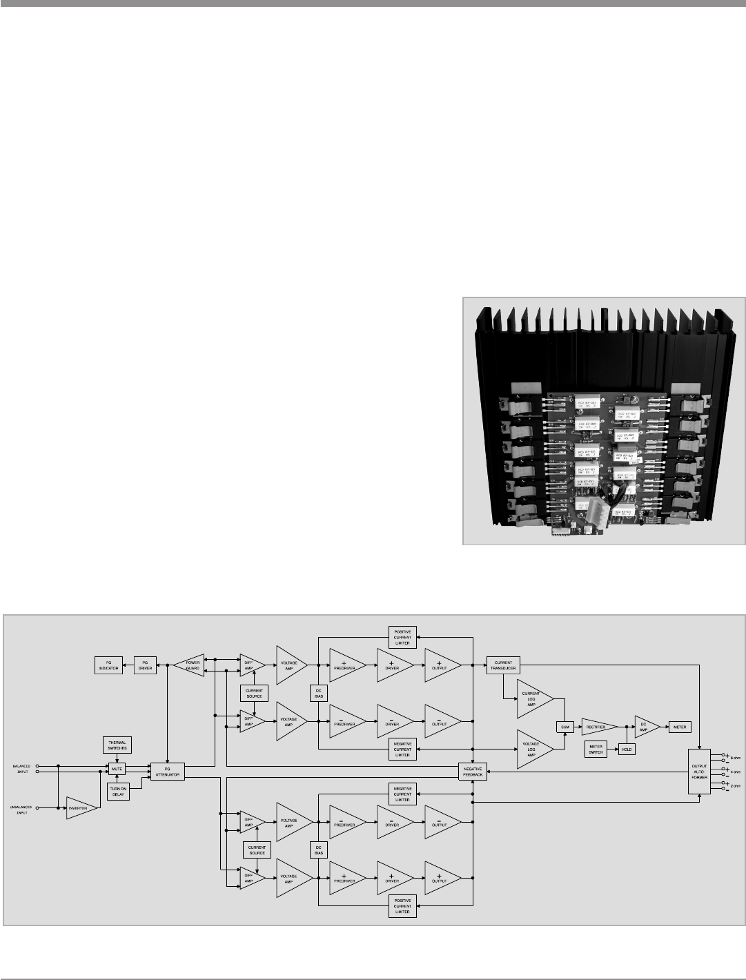
Double Balanced Push-Pull design is used from input to
output. Each half of the amplifier contains complimentary
balanced circuitry. The resulting double balanced configu-
ration cancels even order distortion. Refer to figure 12.
All transistors are selected to have nearly constant
current gain over the entire current range they must cover.
Output transistors in particular, have matched uniform
current gain, high current bandwidth product and large
active region safe operating area. An automatic tracking
bias system completely eliminates any trace of crossover
distortion. Precision metal film resistors and low dielectric
absorption film capacitors are used in all critical circuit
locations.
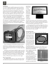
The output signals of the two balanced circuits are
coupled together in the unique McIntosh MC1.2KW Out-
put Autoformer. It provides low distortion power transfer
at frequencies from below 20Hz to well beyond 20,000Hz
with optimum impedance points of two ohms, four ohms
and eight ohms. The unequaled expertise of McIntosh in
the design and manufacturing of autoformers is legendary
in the high fidelity industry.
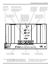
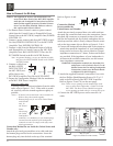
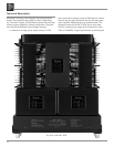
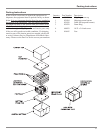
The
high ef-
ficiency
circuit de-
sign of the
MC1.2KW
contrib-
utes to low
operating
tempera-
tures. More
than 2800
square
inches of
heat sink
area keep the MC1.2KW operating safely with convection
cooling. No fans are needed. Refer to figure 13.
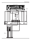
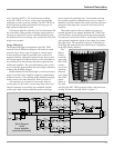
Block Diagram
of the
Power Amplifier
(one channel shown)
Figure 12
Figure 13