Page 4 of 23
11/14/2006 Rev. 14
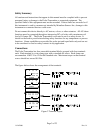
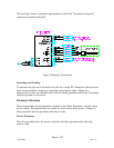
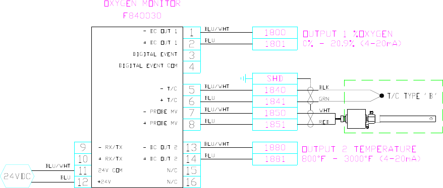
The next figure shows a schematic representation of the Probe Transmitter and typical
connections required in the field.
Figure 3 Schematic Connections
Grounding and Shielding
To minimize the pick-up of electrical noise, the low voltage DC connections and the sensor
input wiring should be routed away from high-current power cables. Where it is
impractical to do this, use shielded cables with the shield grounded at the Probe Transmitter
enclosure ground as show above.
Parameter Selections
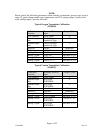
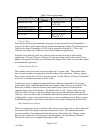
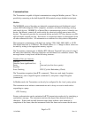
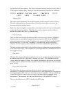
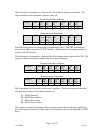
The following tables list the parameters available in the Probe Transmitter. Default values
are also listed. The default values are loaded if a reset is force in the device. Changes to
these parameters must be specified at the time of order.
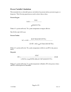
Process Parameters
The following table shows the process selections and other parameters that effect the
process value.


