Page 14 of 23
11/14/2006 Rev. 14
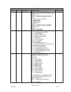
BLOCK 0
HEX DEC PARAMETER DESCRIPTION READ/WRITE
BITS 0 - 4 OXYGEN EXPONENT
RANGE = 0 to 31, where 2 = % and 6 = ppm
DEFAULT = 2
BITS 5 - 6 DISPLAY DECIMAL PLACE
where:
0 = no decimal point in display
1 = Display XXX.X
2 = Display XX.XX
3 = Display X.XXX
DEFAULT = 0
BITS 8 – 12 REDOX METAL NUMBER
RANGE = 0 – 14
DEFAULT = 0
BITS 13 – 15 SPARE
0A 10 FAULT FAULT BIT MAP
BIT 0 = Temperature Input Open
BIT 1 = MV Input Open
BIT 2 = Range of input is low
BIT 3 = Range of input is high
BIT 4 = Timer End
BIT 5 = Probe Care Fault
BITS 6 – 7 = SPARE
BIT 8 = CPU Fault
BIT 9 = Min Idle counter = 0
BIT 10 = Keyboard failure, stuck key or a key
was pressed during power up.
BIT 11 = Flash Erase Failed
BIT 12 = Flash Checksum Failed
BIT 13 = EEPROM Checksum Failed
BIT 14 = Flash/EEPROM Size Fault
BIT 15 = ADC Fault
READ ONLY
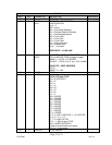
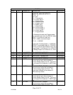
0B 11 ASRC ANALOG OUT SOURCES
LOW BYTE, ANALOG OUTPUT 1
BITS 0 – 3
0000 = N/A
0001 = Temperature
0010 = Linear Input A
0011 = Carbon value
0100 = Dewpoint value
0101 = Oxygen value
0110 = Redox value
0111 = Output Power
1000 = Control Output 1
1001 = Control Output 2
1010 = Linear Input B
1011 = Programmable*
*For Programmable, write required output
value into DACV1, where DACV1 = 0 is
minimum output and
DACV1 = 4096 is maximum output.
BITS 4 – 7 SPARE
READ/WRITE


