


18
ENGLISH
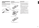
Caution:
• Be sure to use speakers with the specifi ed impedance
as shown on the rear panel of this unit.
• To prevent damage to circuitry, do not let the bare
speaker wires touch each other and do not let them
touch any metal
part of this unit.
• Do not touch the
speaker terminals
when the power is
on. It may cause
you to receive an
electric shocks.
• Do not connect more than one speaker cable to one
speaker terminal. Doing so may damage this unit.
Note:
Be sure to connect the positive and negative cables for
the speaker properly. If they are miss-connected, the
signal phase will be reversed and the signal quality
will be corrupted.
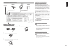
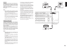
CONNECTING A SUBWOOFER
Use the PRE OUT SUBWOOFER jack to connect a
powered subwoofer (power amplifi er built in).
If your subwoofer is a passive type (power amplifi er
is not built in), connect a monaural power amplifi er to
the PRE OUT SUBWOOFER jack and connect the
subwoofer to the amplifi er.
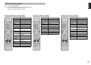
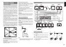
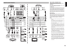
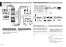
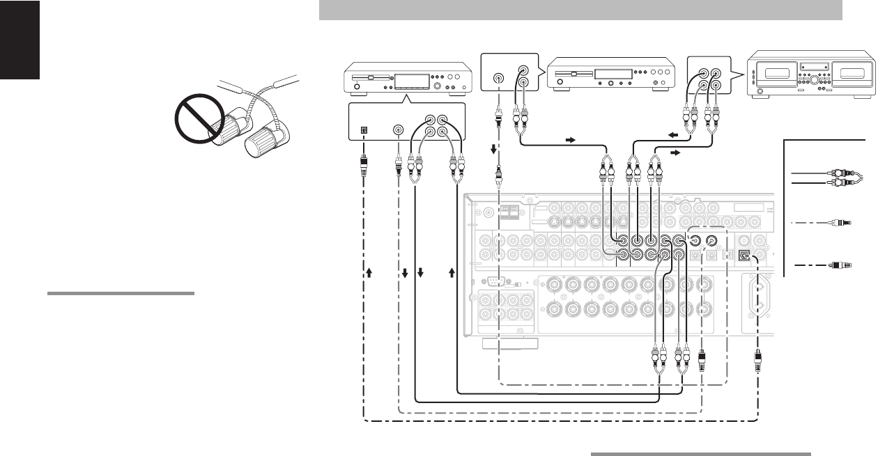
CONNECTING AUDIO COMPONENTS
The output audio signal from the TAPE OUT jack and
the CD-R/MD OUT jack is the same signal which is
currently selected.
Caution:
Do not connect this unit and other components to mains
power until all connections between components have
been completed.
Notes:
• Insert all plugs and connectors securely. Incomplete
connections may make noise.
• Be sure to connect the left and right channels
properly.
Red connectors are for the R (right) channel, and
white connectors are for the L (left) channel.
• Be sure to connect input and output properly.
• Refer to the instructions for each component that is
connected to this unit.
• Do not bind audio/video connection cables with
power cords and speaker cables this will result in
generating a hum or other noise.
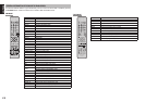
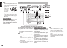
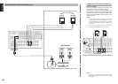
CONNECTING DIGITAL AUDIO COMPONENTS
• There are 4 digital inputs, 2 coaxial jacks and
2 optical jacks, on the rear panel. You can use
these jacks to input PCM, Dolby Digital and DTS
bitstream signals from a CD, DVD, or other digital
source components.
• There is one digital output coaxial jack and one
optical output jack on the rear panel. These jacks
can be connected to a CD recorder-, or a MD deck
inputs, respectively.
• Refer to the instructions for each component. To
setup the digital audio format of DVD player, or
other digital source’s connected to digital input
jacks.
• Use fi ber optical cables (optical) for DIG-1,2,3
input jacks. Use 75 ohms coaxial cables (for digital
audio or video) for DIG-4,5 input jacks.
• You can designate the input for each digital input/
output jacks according to your component. See
page 25.
RS-232C SPEAKER C
OFF ON
FL
RSR
C
SW SBR
SL SBLL
COAX
IN
OUT
RC-5
1
4
3
OPT
DIGITAL OUT
(
AUX2
)
7.1CH INPUT
L SL C SBL
R SR SW SBR
R
L
FM
(
75Ω
)
GNDAM
C
R
/
P
R
C
B
/
P
B
Y
ANTENNA
OUTIN
CDR/MD
OUTIN
TAPECDVCR1DVDTV
AUDIO
DSS/VCR2
ININ OUT
C
R
/
P
R
C
B
/
P
B
YDSS/VCR2TV DVD VCR IN VCR OUT
MONITOR OUT
INPUT
1
INPUT
2
S-VIDEO
VIDEO
PRE OUT
AC OUTLET
230V 50/60H
z
SWITCHED
0.65A 150W
COMPONENT
VIDEO
C
R
/
P
R
C
B
/
P
B
Y
INPUT
3
MONITOR
OUT 2
23
DIGITAL IN
MULTI.
OUT
RR
CENTERSURROUND
R
SURROUND BACK
SPEAKER C/
MULTI SPEAKER
LLLLR
FRONT A OR B.CENTER.
SURR.SURR BACK : 6-8 OHMS
FRONT A + B : 8 OHMS
SPEAKER
SYSTEMS
FRONT B FRONT A
OPT
DIGITAL OUT
DIGITAL INCDR/MDTAPECD
AUDIO
OUTINOUTIN
R
L
3
4
OUT IN
L
R
L
R
OUT
L
R
L R
L R
L R
R L RL
OUT IN
L
R
L
R
DIGITAL
INPUT
DIGITAL
OUTPUT
DIGITAL
OUTPUT
R L
R L R L
RL
L R
R L
CD recorder
CD player
Tape Deck
Analog Audio
Digital Audio (coaxial)
Digital Audio (optical)
Notes:
• There is no Dolby Digital RF input jack. Please use
an external RF demodulator Dolby Digital decoder
when connecting the Dolby Digital RF output jack
of the video disc player to the digital input jack.
• The digital signal jacks on this unit conform to
the EIA standard. If you use a cable that does not
conform to this standard, this unit may not function
properly.
• Each type of audio jack works independently.
Signals input through the digital and analog jacks are
output through the corresponding digital and analog
jacks, respectively.