


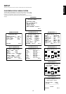

ENGLISH
10
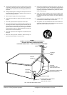
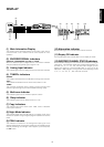
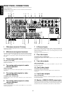
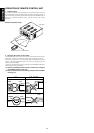
REAR PANEL CONNECTIONS
All connections to the rear panel should be made with the entire
system powered off.
To avoid errors, it is advisable to connect one cable at a time between
the various components.
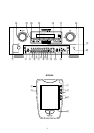
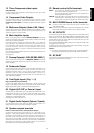
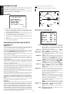
7 6-Channel Inputs
If an external digital audio decoder is used, connect the outputs of
that decoder to these jacks. Note that front L&R channels are
common used in analog audio inputs, use the assigned input in OSD
setup menu system.
(See page 18 “System setup 1/2”.)
8 Five video inputs
TV,LD,DVD, VCR1, and DSS/VCR2 :
Connect each input to the video outputs of your video source
equipment.
9 Two video outputs
VCR1, and DSS/VCR2 :
Connect each output to the video input (REC in) of your video
recording equipment.
10 Five S-video inputs
TV,LD,DVD, VCR1,and DSS/VCR2 :
Connect each input to the S-video outputs of your video source
equipment.
11 Two S-video outputs
VCR1, and DSS/VCR2 :
Connect each output terminals to S-video input (REC in) of your video
recording equipment.
12 Monitor. (VIDEO/S-VIDEO) output jacks
Connect this jack to the composite or S-Video input of a TV monitor or
video projector to view the on-screen menus and the output of any
standard video source selected by the receiver’s video switcher.
AC INLET
AC INLET
AUDIO AUDIO REMOTE CONTROL
VIDEO
COAX
COAX
OUT
OUT
OPT
OPT
OUT
OUT
DIG .1
DIG .1
IN
DIG .2
DIG .2
IN
MULTI
ROOM
DIG .4
DIG .4
IN
IN
DIG .5
DIG .5
IN
IN
DIG .6
DIG .6
/
S - VIDEO
COMPONENT VIDEO
ANTENNA
FM (75
FM (75
Ω
)
GND
GND
AM
AM
RF IN
RF IN
L
R
TV LD DVD IN
–
VCR1
–
OUT
IN
IN
–
DSS/VCR2
DSS/VCR2
–
OUT
OUT
TV LD DVD MONI.VCR1 VCR1
DSS / VCR2
DSS / VCR2
DSS / VCR2
DSS / VCR2
S2 IN S2 IN S2 IN S2 IN
S2 IN S2 OUT
AUDIO
AUDIO
CD IN
–
TAPE
–
OUT
IN
IN
–
CD-R / MD
CD-R / MD
–
OUT
OUT
IN
OUT
REMOTE MULTI
Y Cr
Y Cr
DSS
DSS
/ VCR2
/ VCR2
IN
DVD
DVD
IN
IN
LR
LR
FRONT
FRONT
SURROUND
SURROUND
SPEAKER SYSTEMS 8 OHMS
SPEAKER SYSTEMS 8 OHMS
DIG .3
DIG .3
IN
RL L
FRONT
R L R
(FRONT)
SURROUND
R
WOOFER
SUB
R L
MAIN
IN
OUT
PRE
SURROUNDFRONT
L
SURROUND BACK
L R
CENTER
OUT
OUT
WOOFER
SUB
DIRECT IN
CENTER SURROUND
RL
MONI.
ROOM
MULTI
MONITOR
OUT
IN
VCR1
CENTER
AC OUTLETS
120V 60HZ
SWITCHED 120W 1A
SWITCHED 120W 1A
UNSWITCHED 120W 1A
UNSWITCHED 120W 1A
21 10
11
18 14 1 2 13 221716
19 20 9 5 6 12 3 4 23 24 7 25 26
15
8
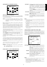
1 FM antenna terminal (75 ohms)
Connect an external FM antenna with a coaxial cable, or a cable
network FM source.
2 AM antenna and ground terminals
Connect the supplied AM loop antenna. Use the terminals marked
“AM” and “GND”. The supplied AM loop antenna will provide good
AM reception in most areas. Position the loop antenna until you hear
the best
3 Three analog audio inputs
CD, TAPE, and CD-R/MD :
Connect the audio outputs of your source components to the input
jacks on the receiver.
4 Two analog audio outputs for audio
source equipment
TAPE and CD-R/MD :
Connect each output to the audio inputs (REC in) of your recording
equipment.
5 Five analog audio inputs for video
source equipment
TV,LD,DVD, VCR1, and DSS/VCR2 :
Connect each input to the audio outputs of your video source
equipment.
6 Two analog audio outputs for video
source equipment
VCR1, and DSS/VCR2 :
Connect each output to the audio inputs (REC in) of your video
recording equipment.