


ENGLISH
13
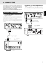
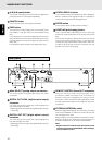
ANALOG BALANCED OUT (analog balanced
output) connector
The signals of the music now playing are output from this
connector.
Using an XLR connector cable, connect the connector to
a component equipped with an analog balanced input
connector.
Note:
* Before connecting the unit to another component,
check that the XLR connectors have the same pin
layout.
If they have a different layout, reconnect the
conductors of the XLR connector cable in such a way
that the pin layouts match.
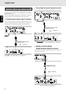
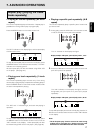
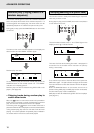
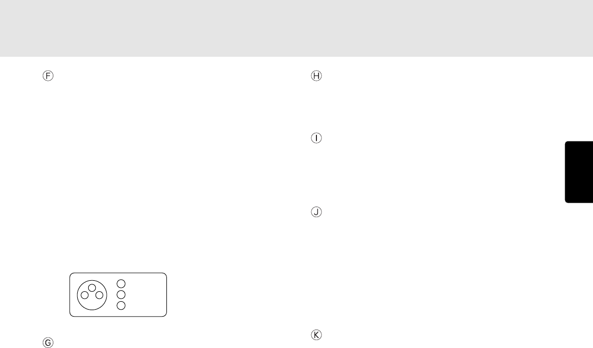
Pin layout of the unit’s XLR connector pins
ANALOG BALANCED OUTPUT LEVEL control
This control is used to adjust the output level of the
ANALOG BALANCED OUT (analog balanced output)
connector.
The output level is increased by turning the control
clockwise.
Note:
* Do not apply excessive force to the control when
adjusting it.
* The output level and channel balance were adjusted
before the unit was shipped from the factory. (Output
level: +16 dBu)
CONTROL I/O (control input/output) connector
This connector is used to connect the remote control input/
output signals. For details, refer to “How to use the
CONTROL I/O (control input/output) connector” (page 41).
RS-232C connector
Using serial communication, the control signals from the
external source and the status information from the unit
are output through this connector. For details, refer to
“How to use the RS-232C connector” (page 43).
DIGITAL OUTPUT (SPDIF) (digital balanced
output) connector
The signals of the music now playing are digitally output
through this balanced output connector.
Use an XLR connector cable to connect the connector
with a component equipped with a digital balanced input
connector.
Digital signals are not output while MP3 files are playing
or during pitch control play.
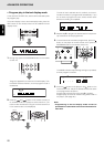
AC POWER SOURCE CONNECTION
With the POWER switch set to the OFF position, plug the
mains lead into a mains outlet providing the right voltage.
1 GND
2 HOT
(+)
3 COLD
(
-
)
2
3
1
NAMES AND FUNCTIONS