6
NAMES AND FUNCTIONS BASIC CONNECTIONS BASIC OPERATIONS
ADVANCED CONNECTIONS
ADVANCED OPERATIONS TROUBLESHOOTING OTHERS
NAMES AND FUNCTIONS
ENGLISH
NAMES AND FUNCTIONS
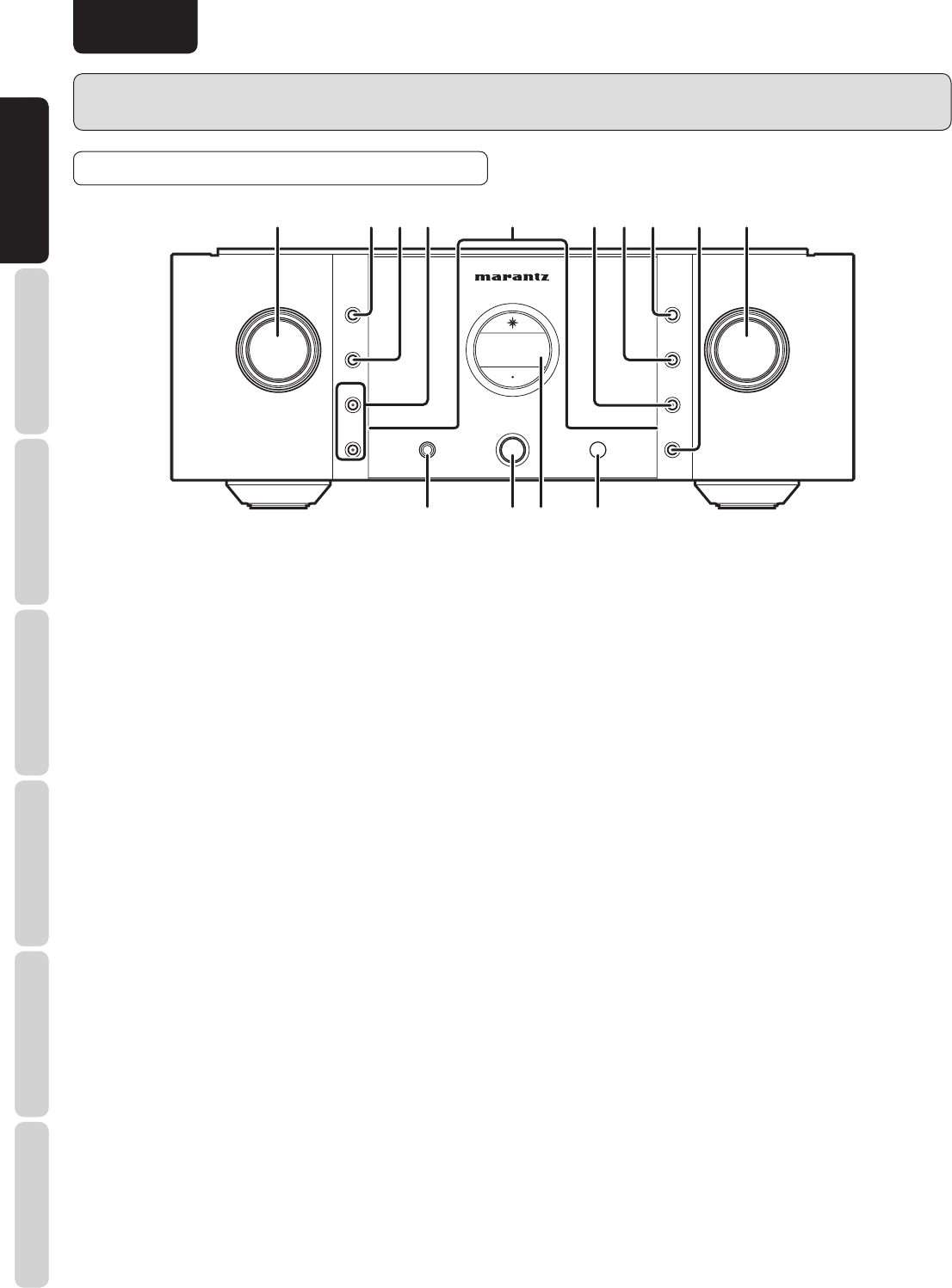
q INPUT SELECTOR Knob
This knob is for selecting the input source to use in
playback and recording. The selected input source is
displayed in the display !2.
w DISPLAY Button
This button turns the display and side illumination ON and
OFF. For instructions on HOW TO OPERATE THE SIDE
ILLUMINATION, see page. 24.
e TONE Button
This button turns the bass and treble tone control ON and
OFF. For instructions on How to Trim Bass and Treble,
see page. 23.
r SPEAKER A/B Buttons
These buttons turn the speaker output to the speakers
connected to the SPEAKER SYSTEM A/B terminals on
the rear panel ON and OFF. To listen with headphones,
turn speaker output OFF.
t Illumination Lamp
The illumination lamp casts a blue light over the switches
and buttons. It can be turned ON and OFF with the
DISPLAY button. For instructions on HOW TO OPERATE
THE SIDE ILLUMINATION, see page. 24.
y REC OUT Button
This button turns the signals output from the RECORDER
1 and 2 OUT jacks on the rear panel ON and OFF.
When RECORDER 1 is selected as the input source,
signals are not output to the RECORDER 1 OUT jack.
The same goes for the RECORDER 2 OUT jack when
RECORDER 2 is selected as the input source.
u PRE OUT Button
This button is for turning the output signal from the PRE
OUT jacks on the rear panel ON and OFF.
i ATT. Button
This button attenuates the volume with one press of the
button. For instructions on How to Set the Attenuation
Level, see page. 24.
o PHONO MC Button
This button switches the phono equalizer between MC
and MM. When MC is set, the center of the button is lit a
blue color. Set the phono equalizer amplifi er according to
the type of cartridge you use.
!0 VOLUME Knob
This knob is for setting the volume. The volume level
is displayed on the display !2. When turned slowly, the
volume can be fi ne-adjusted in 0.5dB steps, whereas when
turned rapidly, the volume level changes greatly.
!1 Infrared Receptor Window
This receptor window receives control signals sent from
the included remote controller.
!2 Display
Indicate the selected input source, volume level, and
setting status.
!3 POWER ON/OFF Switch
This switch turns power to the unit ON and OFF. When
pressed, power is activated and the blue indicator in the
display !2 lights up. Pressing the switch again turns the
power OFF.
!4 PHONES Jack
This jack is for connecting headphones with a standard
stereo plug.
POWER ON/OFF
PHONES
VOLUME
A
TONE
SPEAKER
B
SPEAKER
REC OUT
PRE OUT
ATT.
MC
OPERATE
PHONO
DISPLAY
SELECTOR
INPUT
qwertyuio!0
!1!3
!2!4
FRONT PANEL


