


7
ENGLISH
y
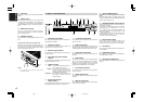
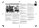
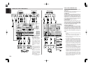
RS-232C
The RS-232C port is to be used in conjunction with
an external controller to control the operation of
the SR7500 by using an external device.
The RS-232C port may also be used in the future
to update the operating software of the SR7500 so
that it will be able to support new digital audio
formats and the like as they are introduced.
u
Preamp Outputs
(L, R, SL, SR, SBL, SBR, C)
Jacks for L(front left), R (front right), C (Center), SL
(surround left), SR (surround right), SBL (surround
back left) and SBR (surround back right).
Use these jacks for connection to external power
amplifiers.
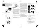
i
AC INLET
Plug the supplied power cord into this AC INLET
and then into the power outlet on the wall.
SR7500 can be powered by 230V AC only.
o
AC OUTLETS
Connect the AC power cable of component such
as a DVD or CD player to this outlet.
The marked SWITCHED provides power only
when the SR7500 is turned on and is useful for
components which you use every time you play
your system.
Caution:
•
In order to avoid potential turn-off thumps, anything
plugged into these outlets should be powered up
before the SR7500 is turned on.
•
The capacity of this AC outlet is 100W. Do not
connect devices that consume electricity more than
the capacity of these AC outlet. If the total power
consumption of the connected devices exceeds the
capacity, the protection circuit shuts down the
power supply.
!0
Speaker outputs terminals
Seven terminals are provided for the front (A) left,
front (A) right, front (B) left, front (B) right, front
center, surround left and surround right speakers.
!1
Speaker outputs terminals (SURROUND
BACK / MULTI SPEAKER / SPEAKER C)
Two terminals are provided for the front left, and
right speakers for multi room (2
nd
zone) or
surround back.
The terminals can be used to connect a third set of
speakers by setting the SPEAKER C selector
switch to ON. For connection and use, see page
17.
!2
Subwoofer Output
Connect this jack to the line level input of a powered
subwoofer. If an external subwoofer amplifier is
used, connect this jack to the subwoofer amplifier
input. If you are using two subwoofers, either
powered or with a 2 channel subwoofer amplifier,
connect a “Y” connector to the subwoofer output
jack and run one cable from it to each subwoofer
amplifier.
!3
7.1 CHANNEL or AUX2 INPUT
By connecting a DVD Audio player, SACD
multichannel player, or other components that has
a multichannel port, you can playback the audio
with 5.1 channel or 7.1 channel outputs.
!4
DC TRIGGER output terminal
Connect a device that needs to be triggered by DC
under certain conditions (screen, power strip,
etc…)
Use the system OSD setup menu to determine the
conditions by which these jack will be active.
Note:
• This output voltage is for (status) control only, It
is not sufficient for drive capability.
!5
Multiroom Outputs (Audio L&R, Video)
These are the audio and video output jacks for the
Multi zone (Multi room).
Connect these jacks to optional audio power
amplifiers or video display devices to listen and
view the source selected by the multiroom system
in a remote room.
!6
MULTI ROOM REMOTE IN/OUT terminals
IN: Connect to a multi-room remote control
device, available from your Marantz dealer.
OUT: Connect to the Marantz component
equipped with remote control (RC-5)
terminals in Multi zone (Multi room).
!7
REMOTE CONT. IN/OUT terminals
Connect to a Marantz component equipped with
remote control (RC-5) terminals.
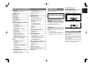
REAR PANEL
e
COMPONENT VIDEO INPUT/OUTPUT
If your DVD player or other device has component
video connectors, be sure to connect them to these
component video connectors on the SR7500. The
SR7500 has 4 component video input connectors
to obtain the color information (Y, C
B
, C
R
) directly
from the recorded DVD signal or other video
component and one component video output
connector to output it directly into the matrix
decoder of the display device.
By sending the pure DVD component video signal
directly, the DVD signal forgoes the extra
processing that normally would degrade the
image. The result is vastly increased image
quality, with incredibly life like colors and crisp
detail.
r
FLASHER IN (Flasher input terminal)
These terminals are to control the unit from each
zone. Connect the control signal from a Keypad,
etc.
t
MONITOR OUT
These are monitor outputs and each one includes
both composite video and S-video configurations.
When connecting two video monitors or televisions,
be aware that the OSD interface can be used with
both MONITOR OUT connections.
q
VIDEO IN/OUT (TV, DVD, VCR1, DSS/VCR2)
These are the video inputs and outputs. There are
4 video inputs and 2 video outputs and each one
includes both composite video and S-video
configurations. Connect VCRs, DVD players, and
other video components to the video inputs.
The 2 video output channels can be used to be
connected to video tape recorders for making
recordings.
w
FM antenna terminal (75 ohms)
Connect an external FM antenna with a coaxial
cable, or a cable network FM source.
AM antenna and ground terminals
Connect the supplied AM loop antenna. Use the
terminals marked “AM” and “GND”. The supplied
AM loop antenna will provide good AM reception in
most areas. Position the loop antenna until you
hear the best reception.
MULTI
OUT
TV DVD
C
IN OUT
S-VIDEO
DVD
DSS/VCR2
C
RS-232C
MULTI RC
IN OUT
DSS/VCR2
IN OUT OUT
VCR1
VCR1
L
SBR
SBL
OUT
PRE
SLL
SRR
DSS/VCR2DVDTV
R
IN
RSW
RC-5
IN
SR
AUDIO
7.1CH
IN
OUT IN
LSL
SBR
SBLCD
IN OUT
SW
OUT
CDR/MDTAPE
OUTIN
IN OUT
VIDEO
MONITOR
OUT
MULTI
VCR1
TV
OUT
(AUX2)
MONITOR
DIGITAL IN DIGITAL OUT
4
1
OPT.
2
5
3
6
COAX.
RL RR
FRONT A
LL
FM
(
75‰
)
ANTENNA
GND AM
COMPONENT
VIDEO
C
B
/
P
B
C
R
/
P
R
C
R
/
P
R
C
R
/
P
R
C
B
/
P
B
C
B
/
P
B
TV
YY
MONITOR OUT
VCR1
DVD DSS/VCR2
Y
SURROUND
100W MAX.
AC OUTLET
SWITCHED
230V 50/60H
Z
OUT
SPEAKER SYSTEMS
FRONT A OR B, CENTER, SURR, SURR BACK
: 6
-
8 OHMS
FRONT A
+
B : 8 OHMS
FLASHER IN
DC OUT
12
12
RL
FRONT B CENTER
SURROUND BACK/
MULTI SPEAKER/
SPEAKER C
ON
OFF
SPEAKER C
OUTPUTINPUT-2INPUT-1
DVI-D
AC IN
tqw e i o
!9 !8
yur
!0
!1!2!4
!7
!6
@0
!5
!5
!3