32
9. WIRING DIAGRAM
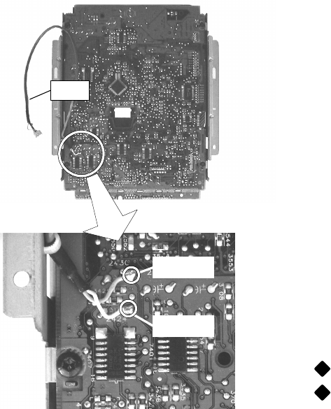
De-soldering and remove cables W651 from the loader
PCB.
REMARK When replace the CDR module MAR775 to
the new one. It is necessary to add removed cables at
same positions as follows;
WHITE + side lead of capacitor 2424
PINK + side lead of capacitor 2430
W651
+ side 2430
+ side 2424
DISMOUNTING ADDITIONAL CABLES
....
.....


