


6
BASIC
CONNECTIONS
BASIC
OPERATIONS
ADVANCED
CONNECTIONS
ADVANCED
OPERATIONS
TROUBLESHOOTING
NAMES AND
FUNCTIONS
OTHERS
NAMES AND
FUNCTIONS
BASIC
CONNECTIONS
ENGLISH
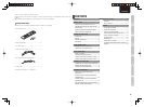
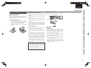
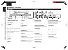
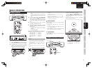
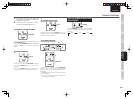
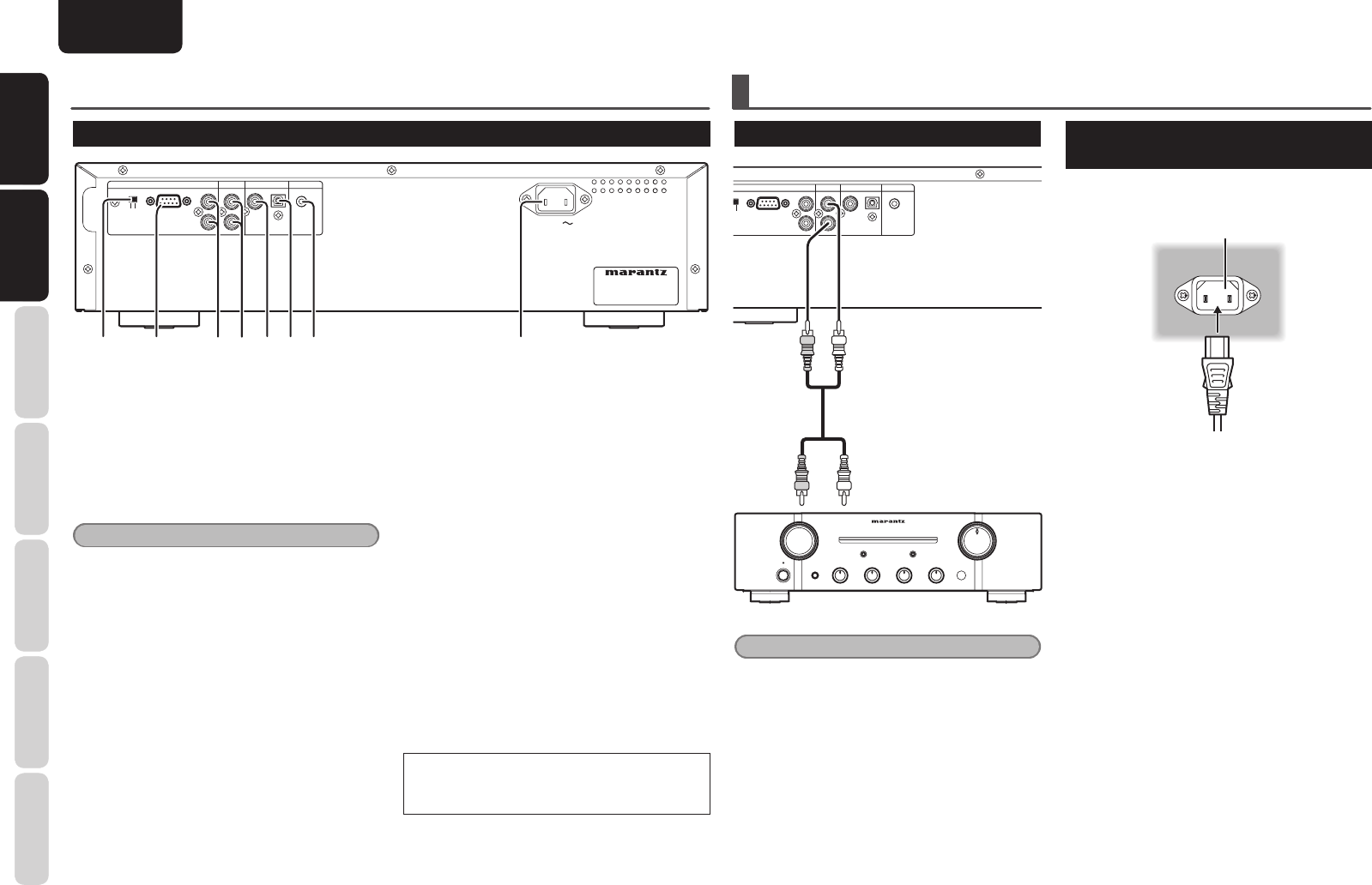
NAMES AND FUNCTIONS
REAR PANEL
AC IN
AC IN
MODEL NO.
MODEL NO.
CC4003
CC4003
RS
RS
-
232C
232C
REMOTE CONTROL
REMOTE CONTROL
ANALOG OUT
ANALOG OUT
OPTICAL
OPTICAL
COAXIAL
COAXIAL
DIGITAL OUT
DIGITAL OUT
R
L
OUT
OUT
IN
IN
INTERNAL
INTERNAL
EXTERNAL
EXTERNAL
FLASHER IN
FLASHER IN
q iert uyw
q EXTERNAL/INTERNAL switch
The switch is set to INTERNAL, when fi rst purchased,
enabling the unit’s built-in signal reception window
to be used.
Before using the supplied connecting cable to make
the connection between the unit and the remote
control connectors on a Marantz equipment, set the
switch to EXTERNAL.
Note
Signals cannot be received from the remote
controller if the switch is kept at EXTERNAL when
the unit is to be used on its own.
w RS-232C connector
A control port for professionals (custom
installers).
e REMOTE CONTROL IN and OUT
connectors
Using the supplied remote control connecting cable,
these connectors enable this unit to be connected
to a Marantz component equipped with remote
control connectors. These connections make it
possible to control an entire system that centers on
the amplifi er or other such component.
r ANALOG OUT connectors
The music signals during play are output from these
connectors.
t DIGITAL AUDIO OUT COAXIAL
connector
The music signals during play are output digitally
from this coaxial output connector.
y DIGITAL AUDIO OUT OPTICAL
connector
The music signals during play are output digitally
from this optical output connector.
u FLASHER IN connector
A control port for professionals (custom
installers).
This is used to control the unit from other
rooms using keypad, etc.
i Power cord connector socket
Use the supplied power cord to connect to a
standard household power supply outlet.
Connect the unit so that the power cord can
be removed easily as a precaution against
possible accidents.
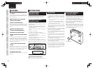
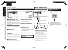
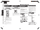
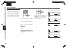
BASIC CONNECTIONS
CONNECTING TO AN AMPLIFIER
RS
RS
-
232C
232C
REMOTE CONTROL
REMOTE CONTROL
ANALOG OUT
ANALOG OUT
OPTICAL
OPTICAL
COAXIAL
COAXIAL
DIGITAL OUT
DIGITAL OUT
R
L
OUT
OUT
IN
IN
INTERNAL
INTERNALEXTERNAL
FLASHER IN
FLASHER IN
Audio connecting cable (supplied)
(Red) (White)
To the CD input connectors
Amplifi er
Notes
• Do not connect this unit and other components
to mains power until all connections between
components have been completed.
• Insert all plugs and connectors securely.
Incomplete connections may make noise.
• Be sure to connect the left and right channels
properly.
• Be sure to connect input and output properly.
• Refer to the instructions for each component that
is connected to this unit.
• Do not bind audio/video connection cables with
power cord and speaker cables this will result in
generating a hum or other noise.
• Do not connect the unit to the PHONO input
connectors on the amplifi er.
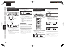
CONNECTING THE POWER
SUPPLY
1. Plug the power cord into AC IN jack on the
rear panel.
AC IN
2. Plug the power cord into an AC outlet.
3. Turn on the power switch of the audio unit
(amplifi er, etc.) that is connected with this
unit. Set the selector on the connected unit
to this unit.