


15
GB
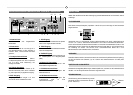
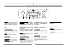
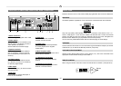
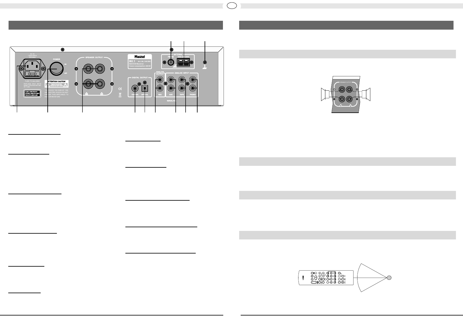
1 Mains connection
For connecting the supplied mains cable.
2 Power switch
Switches the device on and sets it in the
standby mode. If the switch is set to the
"OFF" position, the device is
disconnected from the mains supply.
3 S
peaker terminals
For the connection of stereo speakers
with an impedance rating of 4-8 ohms
(the correct polarity must be taken into
account).
4/5 Digit
al output
s
For the connection of external devices
(e.g. Minidisc recorder) via a coaxial (4)
or optical (5) digital output.
6 REC output
Fixed level output e.g. for the connection
of a tape recorder.
7
AUX input
This is where an auxiliary CD player or
tuner can be connected.
8 T
APE input
For the connection of a cassette
recorder or a tape recorder.
9 PHONO input
Low level input with RIAA equalisation
for record players with a magnetic
system (MM).
10 Earth for phono cable
This is where the earth connection of the
phono cable is screwed.
1
1 AM antenna connection
For connecting the supplied AM loop
antenna.
12 FM antenna connection
For connecting the supplied FM indoor
antenna or a house antenna.
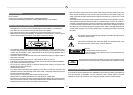
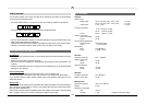
Place the device on a firm, even surface while paying attention to the minimum distances.
SPEAKERS
The stereo speakers (impedance of 4 to 8 ohms) are connected to the rear as follows:
Only use high-quality audio speaker cables with a conductor cross section of min. 1.5 -
2.5mm². Strip approx. 10 mm from the cables and twist the ends. Loosen the terminal
screws one after the other and insert the stripped ends into the holes. Re-tighten the
terminal screws. Make sure you pay attention to the correct polarity.
You can also use prefabricated cables with 4mm banana plugs or forked fittings.
ANTENNAS
Connect the FM indoor antenna or a house antenna (provides better reception) to the rear
of the device (12), as well as the MW loop antenna (if required).
AUXILIARY AUDIO EQUIPMENT
Auxiliary audio devices (MP3 players, record players, etc.) are to be connected to the
appropriate sockets before starting to use the MC 1.
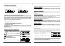
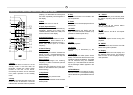
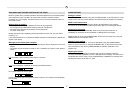
REMOTE CONTROL
When using the remote control aim it at the infrared sensor on the MC 1 (front panel/13).
--
~ 30°
~ 30°
Sensor
right left
12 3 78 964 5
12 1011
OPERATIONAL ELEMENTS AND CONNECTIONS - REAR / CONNECTIONS INSTALLATION