


- 9 -
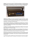
Installation: The DWM-4 operates from an 11 to 15 volt DC power source. The current requirement
is about 75 mA. Be sure to use a power supply or power adapter that meets these requirements.
The coaxial DC jack on the back of the display unit will accept a plug with an OD of 5.5 mm and ID
of 2.5 mm.
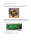
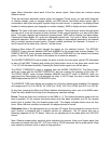
You can use any 50 ohm cable to connect the remote sensor in-line with your antenna system. Be
sure to use the proper cable for your power level. Do not use RG-58 for power levels over 500 watts.
Connect coaxial cable from the transmitter to the SO-239 labeled Transmitter on the remote sensor.
Then connect coaxial cable from the SO-239 labeled Antenna on the remote sensor to your antenna
or antenna tuner.
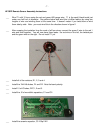
Connect one end of the six-foot, 1/8” stereo cable to the remote sensor. Connect the other end to
input #1 on the DWM-4 display unit.
Other remote sensors (for a total of four) can be connected the same way to other inputs on the
display unit.
Operation: Turning the display unit on will show the model and software version of the DWM-4.
The power LED is software controlled, so it will only come on if the software is running properly. You
may have to adjust the contrast pot (R25) fully counter-clockwise to properly view the LCD module
information. After the display comes on, adjust R25 for best view.
The software will default to channel one and all channels will be configured as numeric display, HF,
150 watt, peak reading sensors with no swr alarms set. The user can now scroll through the menus
with the user interface to select the setup for each channel.
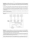
The user interface consists of the LCD, one toggle switch (S1), two pushbutton switches (S2 and
S3) and two LEDs (DS1 and DS2). The LCD provides the operator with a series of menus. Each