


- 3 -
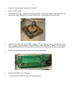
___ Install the socket for U1. Note the orientation of the socket. The flattened corner goes in the upper
left, toward the 14-pin DIP socket for U3. Do not install U1 (the 68HC11) until later.
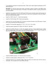
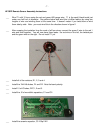
___ Install the 8 MHz crystal.
___ Install the electrolytic capacitor, C2, 10uf radial. Note the polarity.
___ Install the 1/8" stereo jacks, J1-5.
___ Install the power jack, J6.
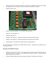
___ Install the 10-pin header, J7. Solder the shorter ends of the pins to the PC board.
___ Install the 14-pin header, J8. Solder the shorter ends of the pins to the PC board.
___ Install the relay K1. Be careful not to bend the pins over pushing them in.
You are finished with the assembly of the DWM-4 Main PC board. Proceed with the assembly of the
Front Panel PC board.
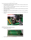
Assembly of the DWM FP PC board.
___ Install the 10 pin header (J7) with 0.1 inch spacing to the side of the front panel PC board that has
the white silk screen. (In copper you can read "Place connector this side". Solder the shorter
ends of the pins to the PC board.
___ Unwrap the chassis (bottom part of the enclosure) and put the 4 rubber feet on the bottom.