- 4 -
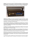
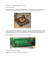
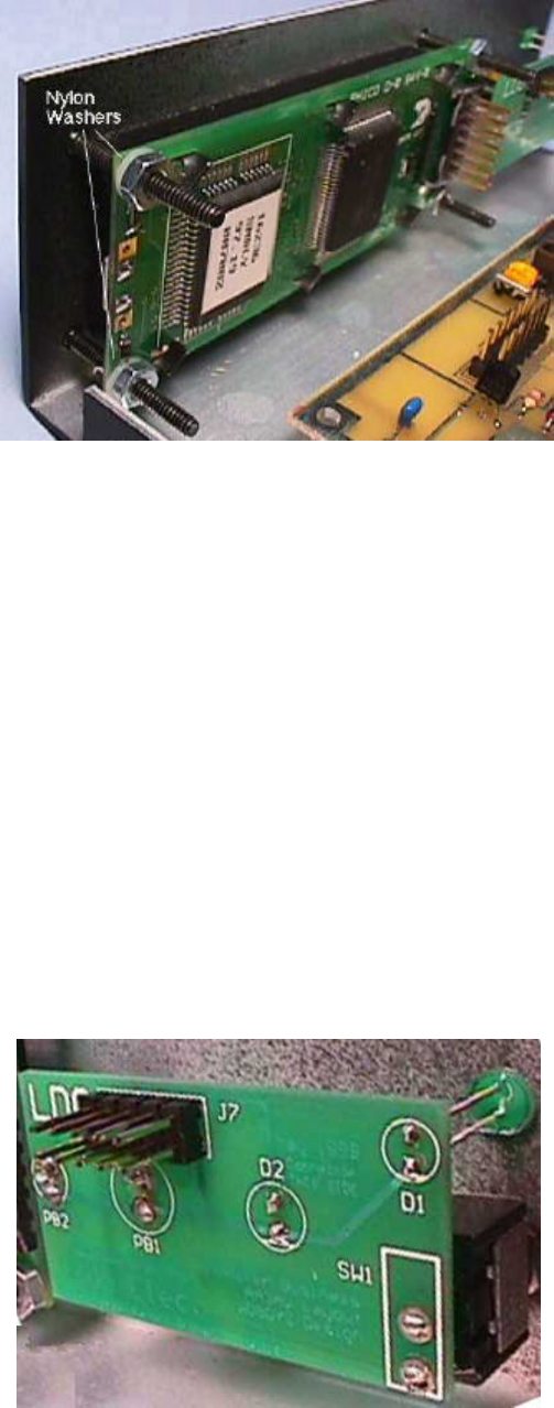
___ Install the LCD Module in the chassis. Use the 4 black flat head screws, the two #4 nylon washers
and four nuts. Use the washers on the Status/SWR side of the chassis. Do not over tighten the
mounting screws.
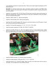
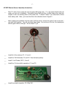
___ Install the SPST toggle switch (SW1) in the chassis in the Power On position. Remove the nut
and one washer from the switch. Place the switch in the hole with the 2 prongs toward the bottom.
Then replace the lock washer and nut on the switch. You may need to re-align the switch later, so
don't tighten yet.
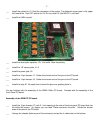
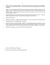
___ Install the 2 push button switches (PB1 & PB2) in the chassis in Menu and Select positions.
Remove the nut and washer from the switch. Place the switch in the hole and replace the washer
and nut on the switch. Be sure the solder terminals of the switches are aligned one on top of the
other. You may need to realign the switches later, so don't tighten yet.
___ Place the LEDs in the front panel board, D1 Green, D2 Yellow. Be sure to place ground side
down. The ground leg of the LED is the one with the notched plastic next to it. Do not solder them
at this time.
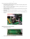
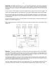
___ Install the Front Panel PC board on the switches. The side without the white silkscreen will be
placed on the solder terminals of the switches. Gently push the pc board onto the switches. The
LEDs should slide into the holes in the chassis. Once you have checked the alignment, then solder
the switches to the pc board. Tighten the nuts on the switches at this time. Next, slide the LEDs
into the chassis and solder the legs to the pc board. Then clip the legs of the LEDs.


