


10
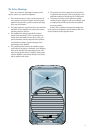
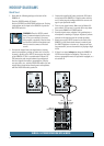
PLACEMENT
The SRM350 v2 active speakers are designed to sit on
the floor, a tabletop, or to fit on a standard tripod speaker
stand. They can also be suspended by the rigging points,
which requires installing the optional hanging bracket on
the top and/or bottom of the cabinet (SRM350 Bracket Kit:
Part No. 0016404). NEVER attempt to suspend the SRM350 v2
active speakers by their handles.
You can lay the cabinet down on its side and use the
SRM350 v2 as a floor monitor. The asymmetrical trapezoidal
shape of the cabinet provides a perfect angle for aiming up
toward performers from the front of the stage.
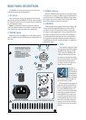
As with any powered components,
protect them from moisture. If you are
setting them up outdoors, make sure
they are under cover if you expect rain.
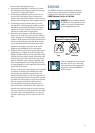
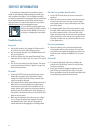
The SRM350 v2 generates a magnetic
field. Do not place it closer than two
feet (0.6 meters) from any TV set or
computer monitor. Check the screen
for any change in color or distortion.
Do not place any magnetic audio or video tapes or
computer discs near the SRM350 v2.
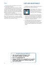
Room Acoustics
The SRM350 v2 active speakers are designed to sound as
neutral as possible; that is, to reproduce the input signal as
accurately as possible, monitoring the sound rather than
changing it.
Room acoustics play a crucial role in the overall
performance of a sound system. However, the wide high-fre-
quency dispersion of the SRM350 v2 helps to minimize the
problems that typically arise.
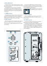
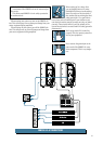
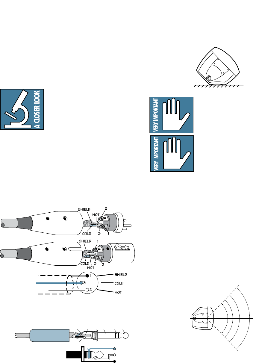
Balanced XLR Connectors
CONNECTIONS
The SRM350 v2 has a combination female XLR and 1/4"
TRS input that accepts a balanced or unbalanced mic- or
line-level signal. When connecting a balanced signal, be
sure it’s wired per AES (Audio Engineering Society) stan-
dards:
XLR TRS
Hot (+) Pin 2 Tip
Cold (–) Pin 3 Ring
Shield (Ground) Pin 1 Shield
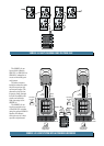
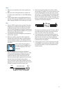
There is also a male XLR connector labeled THRU. This
allows you to connect more than one SRM350 v2 to the out
-
put of your mixing console. Simply plug the signal source
output into the first INPUT jack, and patch that speaker’s
THRU jack to the next INPUT jack, and so on, daisy-chain-
ing multiple speakers (see diagram on page 7).
The THRU jack’s signal comes after
the MIC/LINE switch, but before the
LEVEL control. If the MIC/LINE switch
is pushed in on the first SRM350 v2,
the signal at the THRU jack is boosted
by 40 dB to a line level. Therefore,
leave the MIC/LINE switch out on the following SRM350 v2s
in the chain.
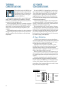
Top
90
0
Dispersion
u
p
to 20 kHz
90
0
SLEEVE
(SHIELD)
TIP (HOT)
TIP
SLEEVE
TIP
SLEEVE
SLEEVE
(SHIELD)
TIP
SLEEVE
TIP (HOT)
RING (COLD)
RING
TIP
SLEEVE
RING
Balanced TRS Connectors