


22
APPENDIX B: Technical Information
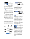
For example, four 8-ohm speakers, con-
nected in parallel, will equal a 2 ohm load
(8 / 4 = 2).
If the parallel loads aren’t all the same,
things gets a little more complicated, but noth-
ing that you can’t do with a simple calculator. The
total impedance (
Z
T
) is given by the following
formula, where
Z
1
, Z
2
and Z
3
are the imped-
ances of your speakers.
Z
T
=
1
1
Z
1
+
1
Z
2
+
1
Z
3
+
. . .
There are other, more complicated configu-
rations, like series-parallel (using a combination
of series and parallel links to arrive at a de-
sired load) and parallel configurations of
unmatched loads (usually not recommended).
But rather than get too deep into this, let’s just
summarize the basics, as they apply to you and
your M•800:
• The lower the speaker impedance, the
more power can be put out by the amplifier.
• Driving lower impedance speakers makes
the amplifier work harder and heat up quicker.
• Do not connect a total impedance of
under 2 ohms per channel in
STEREO
and
MONO
modes.
• Do not connect a total impedance of
under 4 ohms in
BRIDGE
mode.
• Connecting speakers in series or parallel
can drastically alter their frequency response.
• Consider using multiple amplifiers rather
than overloading one.
• Reduce the low-frequency output by set-
ting the
LOW CUT FILTER
to match the
speaker’s specifications.
• Never plug the amplifier outputs into any-
thing except speakers (unless you have an
outboard box designed to accept speaker level
levels).
• Be careful in
BRIDGE
mode as both
speaker wires are live. In this mode, do not
connect the speaker wires to any external de-
vice which is grounded.
SPEAKER IMPEDANCES
A speaker’s impedance varies with fre-
quency. For example, it may be 4 ohms at
500Hz, and 6 ohms at 120Hz. What you need to
know is the average (or nominal) impedance
across the speaker’s frequency range. This will
be printed somewhere on the cabinet, or in the
specification section of the missing manual.
If you’re just dealing with one speaker per
channel, then make sure that the average im-
pedance is greater than or equal to 2 ohms.
In
BRIDGE
mode, make sure that your
speaker is greater than or equal to 4 ohms.
If you’re driving an assortment of speakers,
you have to make sure that the total imped-
ance does not go below these same levels.
There are two basic ways of linking multiple
speakers: series and parallel. The following sec-
tions show how to make the connections and
how to work out the total impedance.
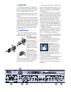
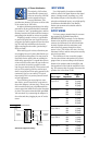
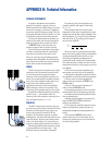
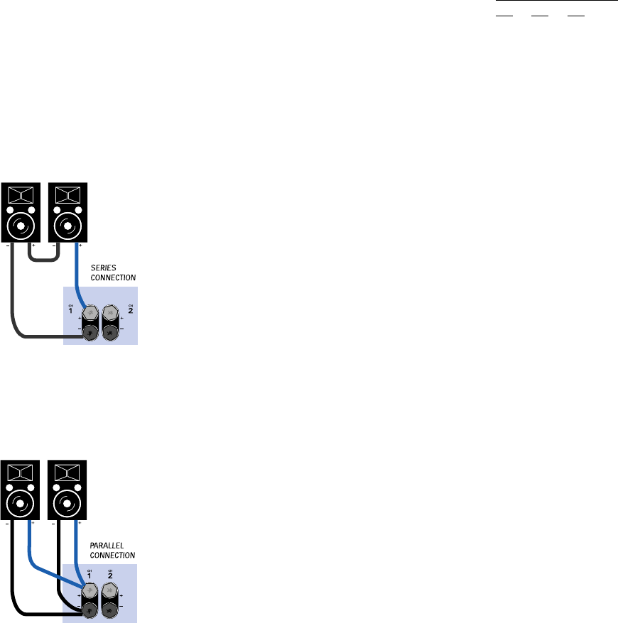
SERIES
“Series” means that the positive amp output
connects to the first speaker’s positive termi-
nal, the first speaker’s negative terminal
connects to the second speaker’s positive ter-
minal, the second speaker’s negative terminal
goes to the amp’s negative output. Series con-
nections are not normally used in PA
applications because it ruins the amplifier’s
ability to damp (control) the speakers. The
other snag: if one speaker goes out, they all do.
Doing load calculations with series configu-
rations is easy — just add the loads. For
instance, two 4-ohm speakers, connected in se-
ries, will equal 8 ohms (4 + 4 = 8).
PARALLEL
“Parallel” means that the positive amp out-
put connects to the positive terminals of all the
speakers, and the negative amp output con-
nects to the negative terminals of all the
speakers. If one speaker opens in a parallel
configuration, the others will still work, but the
load will change. That lets you breathe a little
easier (the show will go on), except that you
may have a dead speaker and not even know it.
Calculating parallel loads is also easy, as long
as each speaker has the same value — just
divide the value by the number of speakers.