


IB-HT400-WM-E-122502
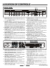
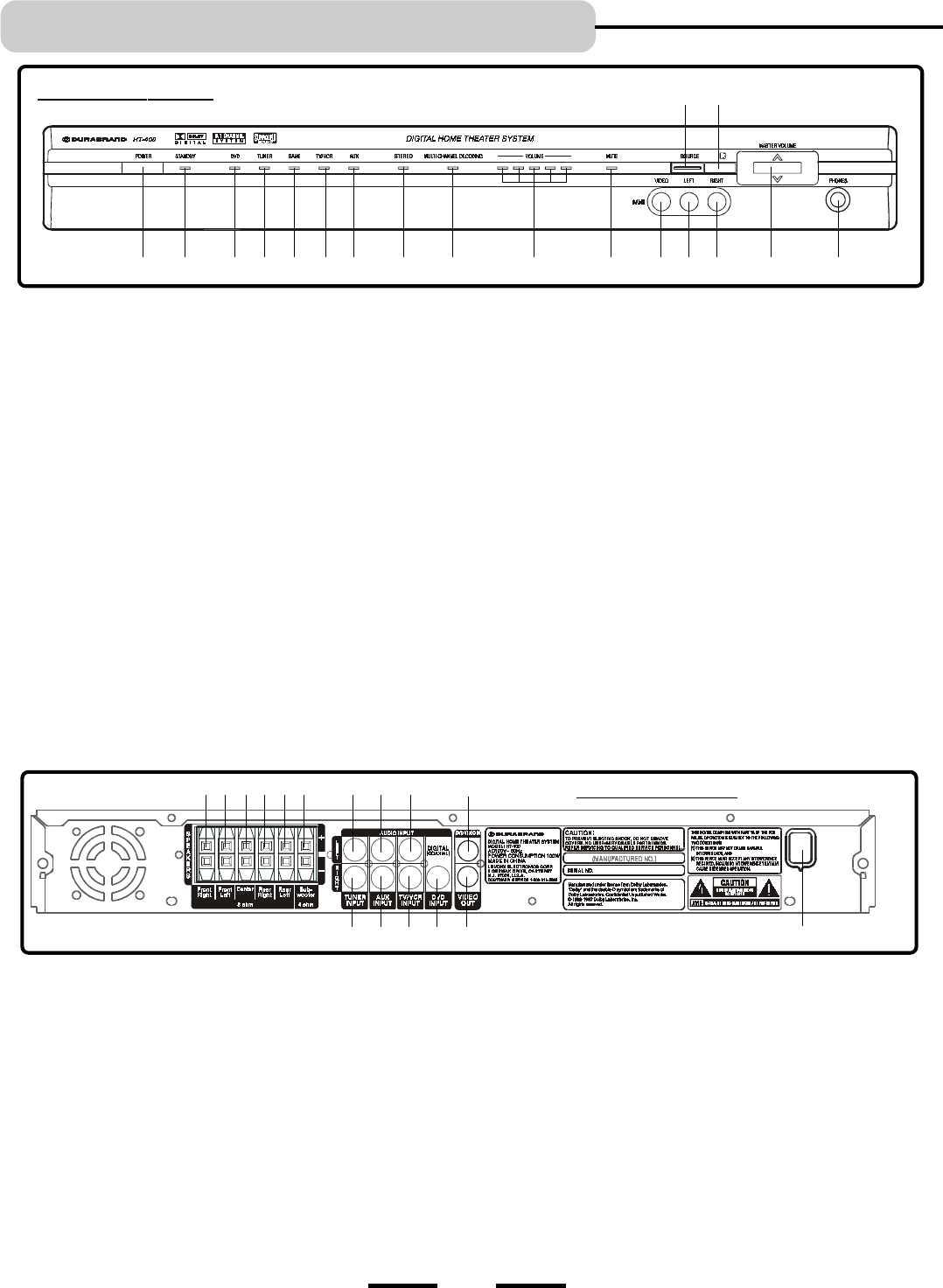
1. MAIN POWER button - Press to switch the set on or off.
NOTE: This button must be on in order to be able to use
the REMOTE control.
2. STANDBY indicator - This indicator has 2 colors: red and
green (red is standby, green is on). When the set is off
(standby), pressing the SOURCE or MASTER VOLUME
buttons on the main unit, or pressing any button on the
REMOTE CONTROL will turn the set on. The indicator will
become green. Also this indicator will flash confirming that
you pressed any button on the REMOTE CONTROL.
3. DVD indicator - For DVD sound use, press the SOURCE button
till this lights or press the DVD button on your REMOTE control.
4. TUNER indicator - For AM/FM TUNER sound use, press
the SOURCE button till this lights or press the TUNER button
on your REMOTE control.
5. GAME indicator - For TV GAME or VIDEO CAMERA use,
press the SOURCE button till this lights or press the GAME
button on your REMOTE control.
6. TV/VCR indicator - For TV/VCR sound use, press the
SOURCE button till this lights or press the TV/VCR button on
your REMOTE control.
7. AUX indicator - For AUX IN sound use, press the SOURCE
button till this lights or press the AUX button on your
REMOTE control.
LOCATION OF CONTROLS
8. STEREO indicator - In STEREO mode, this red indicator
lights up (for 2 channel sound).
9. MULTI CHANNEL DECODING indicator - When the
input source is Dolby Digital, DTS or PRO LOGIC, this
blue indicator lights up (for 5.1 channel sound).
10.VOLUME indicators - These indicators light up
showing the level of the master volume.
11. MUTE indicator - In mute mode, this indicator will light.
12. VIDEO IN jack - For connection of a video signal from a
TV game or video camera (see details on Page 16 & 17).
13. AUDIO LEFT jack - Connect to the left channel audio
output of a TV game or video camera.
14.AUDIO RIGHT jack - Connect to the right channel
audio output of a TV game or video camera.
15. MASTER VOLUME UP & DOWN control - Increases or
decreases the volume level of all speakers.
16. PHONES jack - For connecting stereo headphones.
17. REMOTE CONTROL SIGNAL sensor - Receives the
signal from the REMOTE CONTROL (Aim the REMOTE
control towards this sensor).
18. SOURCE button - Press several times to select the sound
input source you want: DVD, TUNER, GAME, TV/VCR, or AUX.
4
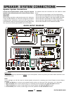
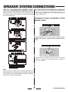
1. FRONT RIGHT SPEAKER jacks - Connect the FRONT
RIGHT SPEAKER to the red and black terminals.
2. FRONT LEFT SPEAKER jacks - Connect the FRONT
LEFT SPEAKER to the red and black terminals.
3. CENTER SPEAKER jacks - Connect only the CENTER
SPEAKER to the blue and black terminals.
4. REAR RIGHT SPEAKER jacks - Connect the REAR
RIGHT SPEAKER to the grey and black terminals.
5. REAR LEFT SPEAKER jacks - Connect the REAR
LEFT SPEAKER to the grey and black terminals.
6. SUBWOOFER SPEAKER jacks - Connect the
SUBWOOFER SPEAKER to the green and black terminals.
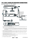
7. TUNER AUDIO INPUT jacks - Connect to the audio
output of your AM/FM TUNER.
8. AUX AUDIO INPUT jacks - Connect to the audio
output of a tape deck or other component.
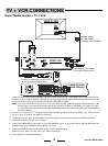
9. TV/VCR AUDIO INPUT jacks - Connect to audio output
of a TV or VCR.
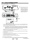
10.DVD AUDIO INPUT jacks - Connect to the
digital (coaxial) audio output of a DVD player to have
Dolby Digital, DTS 5.1 channel surround sound.
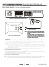
11. VIDEO OUT jack - Connect to your TVs video input jack.
(If your TV has no VIDEO jack, you have to buy a VIDEO
RF MODULATOR.)
IMPORTANT: This jack is only used if you are connecting
a TV GAME or VIDEO CAMERA to the set.
12.AC LINE CORD - Connect to a 120V/60Hz AC
standard wall outlet.
13. DVD VIDEO IN jack - Connect to your DVDs video out jack.
2134
FRONT PANEL
5 6 7 89 10 11 12 13 14 15 16
18 17
BACK PANEL
1 2
3
4
5
6
8
7
11
9
810
1279
13