


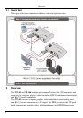
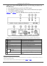
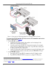
Connecting the TP-145 and the TP-146
7
7
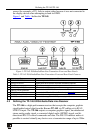
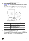
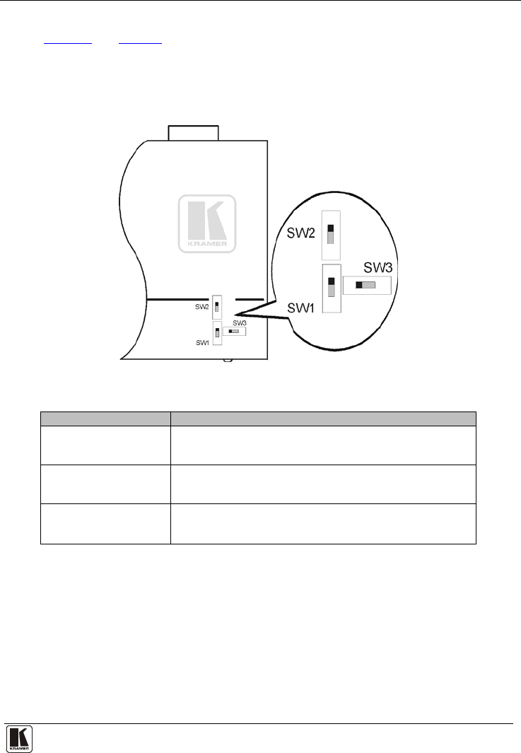
4.2.1 Internal Polarity and Sync Mode Switches
Figure 3 and Table 3 define the internal horizontal and vertical polarity switches of
the TP-146.
Note: You need to open the TP-146 unit to gain access to the Hs and Vs polarity
and video selection switches which are located on the lower part of the printed
circuit board next to the ON LED. After setting the switches, close the TP-146.
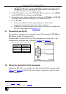
Figure 3: TP-146 Internal Polarity Switches
Table 3: TP-146 Internal Polarity Switches and Descriptions
Switch/Jumper Function
SW1 Horizontal Sync Switch Slide up to set the H Sync to positive polarity
Slide down to set the H Sync to negative polarity
Default = up (positive polarity)
SW2 Vertical Sync Switch Slide up to set the V Sync to positive polarity
Slide down to set the V Sync to negative polarity
Default = up (positive polarity)
SW3 Video Selection Switch Slide left to set the video to RGBHV/VGA
Slide right to set the video to Component/Composite video with sync
Default = left (RGBHV/VGA video)
5 Connecting the TP-145 and the TP-146
You can use the TP-145 UXGA/Audio/Data Line Transmitter and the TP-146
UXGA/Audio/Data Line Receiver to configure a TP transmitter and receiver system
that transmit video, audio, and RS-232 control signals via TP cable.