


Contents
i
Contents
1 Introduction 1
2 Getting Started 1
2.1 Quick Start 2
3 Overview 2
3.1 Shielded Twisted Pair/Unshielded Twisted Pair 3
3.2 Defining the EDID 3
3.3 Recommendations for Achieving the Best Performance 4
4 Defining the TP-145/TP-146 4
4.1 Defining the TP-145 XGA/Audio/Data Line Transmitter 4
4.2 Defining the TP-146 UXGA/Audio/Data Line Receiver 5
4.2.1 Internal Polarity and Sync Mode Switches 7
5 Connecting the TP-145 and the TP-146 7
5.1 Transmitting via RS-232 9
5.2 Wiring the Twisted Pair RJ-45 Connectors 9
6 Acquiring the EDID 10
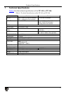
7 Technical Specifications 11
Figures
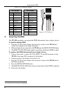
Figure 1: TP-145 XGA/Audio/Data Line Transmitter Front and Rear Panels 5
Figure 2: TP-146 UXGA/Audio/Data Line Receiver Front and Rear Panels 6
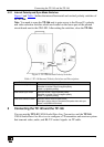
Figure 3: TP-146 Internal Polarity Switches 7
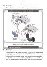
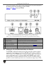
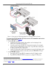
Figure 4: Connecting the UXGA/Audio/Data Line Transmitter/Receiver System 8
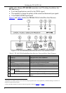
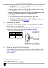
Figure 5: RS-232 Pinout Connection 9
Figure 6: TP Connector 10
Tables
Table 1: TP-145 XGA/Audio/Data Line Transmitter Front and Rear Panel Features 5
Table 2: TP-146 UXGA/Audio/Data Line Receiver Front and Rear Panel Features 6
Table 3: TP-146 Internal Polarity Switches and Descriptions 7
Table 4: RS-232 Pinout Connection 9
Table 5: TP Connector Pinout 10
Table 6: Technical Specifications of the TP-145 and TP-146 11