


Connecting the TP-145 and the TP-146
9
9
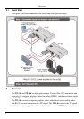
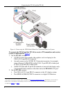
An RS-232 cable with a 3 pin terminal block connector at one end to the
TP-146 RS-232 port
1
3. Using STP cabling
, and a 9-pin D-SUB connector at the other end to
the RS-232 port on the AV display system
2
4. Connect the power adapter to the power socket on the TP-145 and/or TP-146
(if needed), and connect the adapter(s) to the mains electricity.
, connect the LINE OUT RJ-45 connector on the TP-145
to the LINE IN RJ-45 connector on the TP-146.
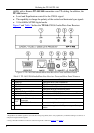
5. On the TP-146:
If necessary, adjust the video output signal level and/or cable
compensation equalization level with a flat screwdriver
If necessary, set the horizontal sync switches, vertical sync switches, and
the sync mode jumpers (see Section
4.2.1)
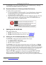
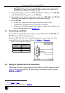
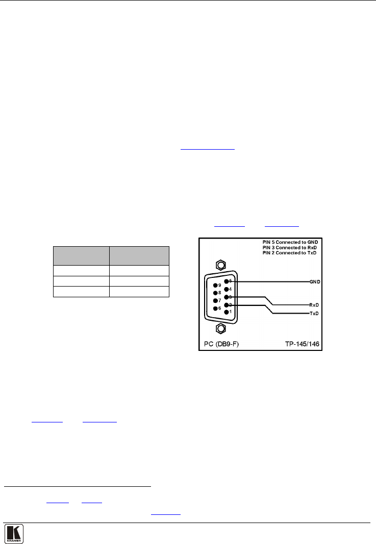
5.1 Transmitting via RS-232
It is possible to transmit data (for example, using a PC) between the TP-145 and
TP-146 via the RS-232 terminal block.
Prepare an RS-232 cable with a 9-pin D-sub connector at one end, and a 3 pin
terminal block at the other end as defined in
Table 4 and Figure 5.
Table 4: RS-232 Pinout Connection
Terminal
Block
9-pin D-sub
Connector
TxD Pin 2
RxD Pin 3
GND Pin 5
Figure 5: RS-232 Pinout Connection
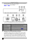
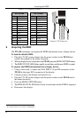
5.2 Wiring the Twisted Pair RJ-45 Connectors
When using STP cable, connect/solder the cable shield to the RJ-45 connector shield.
Table 5 and Figure 6 define the TP pinout using a straight pin-to-pin cable with
RJ-45 connectors.
1 As defined in Figure 5 and Table 4
2 For details of how to wire a TP RJ-45 connector, see Section
5.2