


6 TP-133/TP-134 - Defining the TP-133/TP-134 Line Transmitter and Receiver
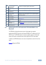
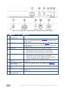
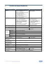
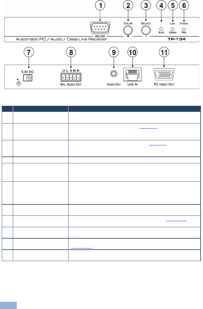
Figure 2: TP-134 Automatic PC/Audio/Data Line Transmitter Front and Rear Panels
# Feature Function
1 RS-232 9-pin D-sub
Connector (M)
Connect to the controlled RS-232 device (monitor)
2 COLOR / + Button Press to enter the setting mode (see Section 6
Press and hold together with the SELECT button to trigger the auto-
adjust function
).
3 SELECT / – Button Press to select the setting to change (see Section 6
Press and hold together with the COLOR button to trigger the auto-
adjust function
).
4 BLUE LED Flashes to indicate that the blue color setting is selected
5 LINK / GREEN LED
• Lights orange to indicate that the TP link is established
• Flashes orange to indicate that there is a link problem
• Flashes green to indicate that the green color is selected
6 POWER / RED LED
• Lights green to indicate that the device is receiving power
• Flashes red to indicate that the red color is selected
• Flashes red together with the GREEN LED flashing green) to
indicate that the equalization setting is selected
7 5.3V DC Power
Connector
Connect to one of the supplied +5.3V DC power adapters. Center
pin positive
8 BAL. AUDIO OUT 5-pin
Terminal Block
Connect to a balanced, stereo audio acceptor (see Section 5.1
9
)
AUDIO OUT 3.5mm Mini
Jack
Connect to an unbalanced, stereo audio acceptor
10 LINE IN RJ-45 Connector
Connect to the LINE OUT RJ-45 connector on the TP-133 (see
Section 5.2
11
)
PC VIDEO OUT 15-pin
HD Connector (F)
Connect to a computer graphics video acceptor