


Chapter 4: Front Panel
DN530
14 Operator Manual
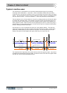
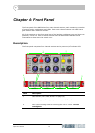
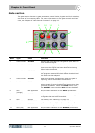
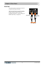
Gate section
The gate section houses six gate parameter control knobs, bypass and duck switches,
and a set of six metering LEDs. For more information on the gate controls and their
uses, see Chapter 6 "Gate Control Functions" on page 19.
Item Type Label Function
1 Control knob ATTACK Adjusts the time taken for the gate to open after an
over-threshold signal.
2 Control knob HOLD Defines a waiting period before the gate starts to
close once the signal has been detected as having
fallen below threshold.
3 Control knob RELEASE Adjusts the time its takes for the gate to close after
the program material falls back below threshold and
the hold time has elapsed.
4 Control knob ACCENT Adds an overshoot characteristic when the gate is
opening, which accentuates the transient.
5 Pushbutton DUCK Reverses the operation of the gate so that it closes
when signals go over threshold and opens when they
go below threshold. When the DUCK switch is on,
the ACCENT control and the ACC LED are disabled.
6LED
(orange)
Not applicable On/off status indicator for the DUCK pushbutton.
7 Control knob RANGE Adjusts the amount of gain reduction that is applied
to signals that are below threshold.
8 LED Various For details, see “Metering” on page 15.
9 Control knob THRESHOLD Adjusts the operating point (threshold) of the gate.
10 Pushbutton BYPASS Disconnects the gate from the main signal path.
11 LED (red) Not applicable On/off status indicator for the BYPASS pushbutton.
3
2
4
5
6
7
8
9
10
11
1