


Chapter 3: Getting Started
DN530
12 Operator Manual
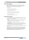
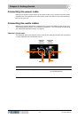
Connecting to unbalanced equipment
Ideally, you will be making the best use of the DN530’s low-noise high-headroom
balanced inputs by connecting to similarly balanced equipment. However, if you do
have to connect to unbalanced devices, the following wiring is recommended for best
results (see Figure 3):
• Connect the +ve (pin 2) of the balanced connection to the +ve terminal on the
unbalanced connector.
• Connect the -ve (pin 3) of the balanced connection to the common (ground) terminal
on the unbalanced connector.
• Connect the ground (pin 1) of the balanced connection to the common (ground)
terminal on the unbalanced connector.
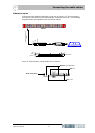
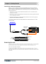
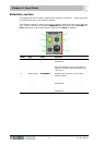
The following diagram shows the wiring details for the insert send/return 1/4” TRS
connector/XLRs.
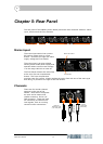
Powering the unit
To power up the unit, switch on the power at the mains power outlet. The blue power
LED on the front of the unit (far right) will illuminate to show that power is on.
Your unit is now ready to operate.
To switch off the DN530, switch off the mains at the mains power outlet. Then, to
electrically isolate the unit, remove the mains cable from the mains IEC socket on the
rear panel.
Tip
Sleeve
Ring
To sidechain socket
DN530 (rear panel)
Console
Female XLR
Male XLR
Female XLR
Tip
Ring
Sleeve
1
2
3
1
2
3
Male XLR
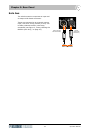
Single channel
connections on
rear of unit