


9
English
110V
127V
220V
230 -
240V
TV
VCR
DBS
IN
IN
IN
(PLAY)
DBS
IN
VCR
MONITOR
OUT
IN
(PLAY)
Å
ı
Ç
110V
127V
220V
230 -
240V
VCR
DBS
IN
IN
(PLAY)
OUT
(REC)
DVR/DVD
IN (PLAY)
Y P
B
P
R
MONITOR
OUT
DVR/DVD
IN
VCR
IN
COMPONENT
DBS
IN
VCR
OUT
(REC)
IN
(PLAY)
DVR/DVD
IN (PLAY)
‰
ÏÌ
Î
Ç
Å ı
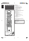
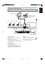
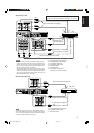
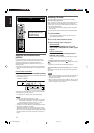
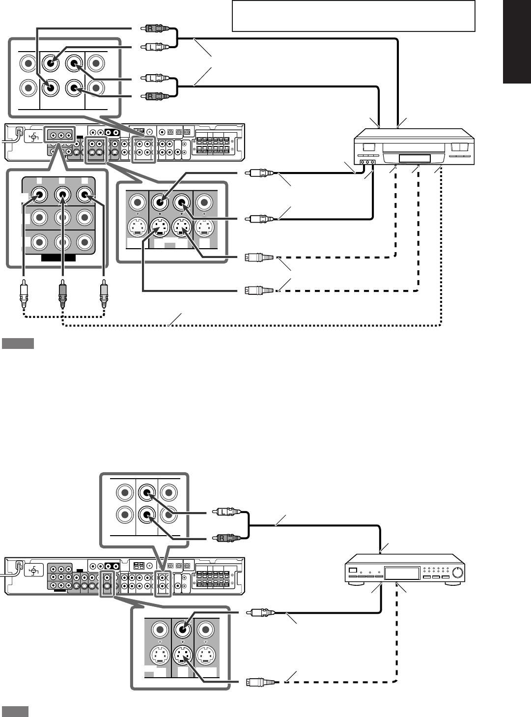
7 Connecting a VCR
Å To left/right audio channel output
ı To left/right audio channel input
Ç To composite video input
Î To composite video output
‰ To S-video output
Ï To S-video input
Ì To component video output
• Connect Y, P
B, and PR correctly.
Stereo audio cable (not supplied)
White
Red
White
Component video cable (not supplied)
Composite video
cable (not supplied)
S-video cable (not supplied)
Red
Green Blue Red
VCR
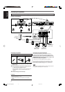
NOTES
• When connecting a VCR to the component video input jacks,
make the component video input setting (VCR VIDEO INPUT)
correctly. If you do not, you cannot view the playback picture on
the TV or the AV COMPU LINK remote control system cannot
operate properly. For details, see page 25.
•You can enjoy digital sound if using a digital coaxial or optical
cable. When shipped from the factory, the audio input mode for
a video component other than DVD recorder and DVD player is
set to use the digital optical terminal (DIGITAL IN 3 (VCR)). For
details of digital connection, see page 11.
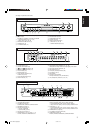
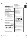
Turn off all components before making connections.
• When you connect other components, refer also to their manuals.
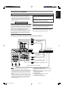
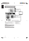
Stereo audio cable (not supplied)
Composite video cable (not supplied)
DBS tuner
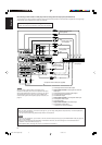
NOTE
You can enjoy digital sound if using a digital coaxial or optical
cable. When shipped from the factory, the audio input mode for a
TV is set to use the digital optical terminal (DIGITAL IN 2 (DBS)).
For details of digital connection, see page 11.
White
Red
S-video cable (not supplied)
7 Connecting a DBS tuner
Å To left/right audio channel output
ı To composite video output
Ç To S-video output
EN06-11RXF31S[US]FF.p65 05.6.9, 18:329