


z
0
-
....
u
w
z
z
·o
u
..........
z
0
-
....
cc
....
....
cc
....
"'
z
-
16
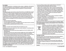
A
Warning
•
The
unit
can
only
be
used
with
a
12
V
DC
power
supply,
negative'ground.
•
Disconnect
the
battery's
negative
terminal
before
wiring'
and
mounting.
•
Do
not
connect
Battery
wire
(yellow)
and
Ignition
wire
(red)
to
the
car
chassis
or
Ground
wire
(black)
to
prevent
a
short
circuit
•
Insulate
unconnected
wires
with
vinyl
tape
to
prevent
a
short
circuit.
•
Be
sure
to
ground
this
unit
to
the
car's
chassis
again
after
i~stallation.
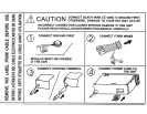
A
Caution
•
For
safety's
sake,
leave
wiring
and
mounting
to
professionals.
Consult
the
car
audio
dealer.
•
Install
this
unit
in
the
console
of
your
vehicle.
Do
not
touch
the
metal
parts
.
of
this
unit
during
and
shortly
after
use
of
the
unit.
Metal
parts
such
as
the
heat
sink
and
enclosure
become
hot.
•
Do
not
connect
the
8
wires
of
speakers
to
the
car
chassis
or
Ground
wire
(black),
or
connect
them
in
parallel.
~
Connect
speakers
with
a
maximum
power
of
more
than
50
W.lf
the
maxim_um
power
of
the
speakers
is
lower
than
50
W,
change
the
[AMP
GAIN]'
setting
to
avoid
damaging
the
speakers.
(+11)
•
Mount
the
unit
at
an
angle
of
less
than
30°.
• If
your
vehicle
wiring
harness
does
not
have
the
ignition
terminal,
connect
Ignition
wire
(red)
to
the
terminal
on
the
vehicle's
fuse
box
which
provides
12
V
DC
power
supply
and
is
turned
on
and
off
by
the
ignition
key.
•
After
the
unit
is
installed,
check
whether
the
brake
lamps,
blinkers,
wipers,
etc.
on
the
car
are
working
properly.
• If
the
fuse
blows,
first
make
sure
the
wires
are
not
touching
car's
chassis,
then
replace
the
old
fuse
with
one
that
hasthe
same
rating.
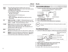
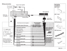
Basic
procedure
1 Remove the key from the ignition switch, then
disconnect the
8
terminal
of
the car battery.
2 Connect the
wire$
properly.
See
Wiring connection.
(+17)
3
·Install
the unit to your
car.
..
See
Installing
the
unit
(in-dash
mounting).
4 Connect the
8
terminal
ofthe
car
battery.
·
S Reset the
unit.(+
3)
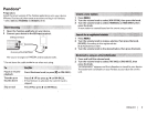
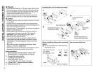
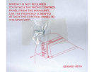
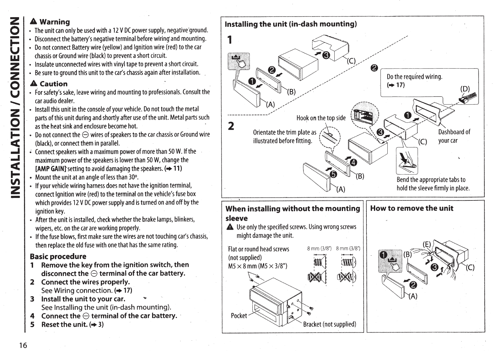
Installing
the
unit (in-dash mounting)
1
Do
the
requi
.
red
wiring.
"
..
"
....
~
...
·.
-
.·
-
.·.·
. .
(D)
~
! dt
~f~;
~l~
.
~
'
·•'••
V ..,"'
Hoo~
on
the
top
side
\
(+17)
.
2
Orientate
the
trim
plate
as
/
~~~;
~
...
\
illustrated
before
fitting.
\,,)
'
"
'
.....
-,
r
:~
;,
:
··
.·.,
..
··
·
...
·.··.
··
...
··
..
·· ....
···'
...
·'
..
1
~~/~
,
·.
,.-.:
f~
_,
.....
I
......
.
'/
. ,
........
1
~--,,:\
a
r:<~
..............
~
.
.,,~
""~
,,
,
......
'~~.)."..,...""''\\
Dashboard
of
(C)
your
car
~~B)
~A)
~
Bend
the
appropriate
tabs
to
hold
the
sleeve
firmly
in
place.
When
installing
without
the mounting
II
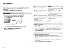
How
to
remove
the
unit
sleeve
A
Use
only
the
specifi.ed
screws;
Using
wrong
screws
might
damage
the
unit.
'
Flat
or
round
head
screws
8
mm
(3/8")
8
mm
(3/8")
(not
suppHed)
i1
-
~
M5
X
8
mm
(M5
X
3/8")
\'~~
~
...........
.(]
~~
""l
~~~
~
B:cket
(not
supplied)