


ELECTRICAL CONNECTIONS
2
A
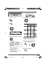
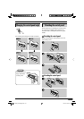
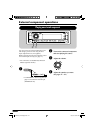
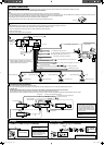
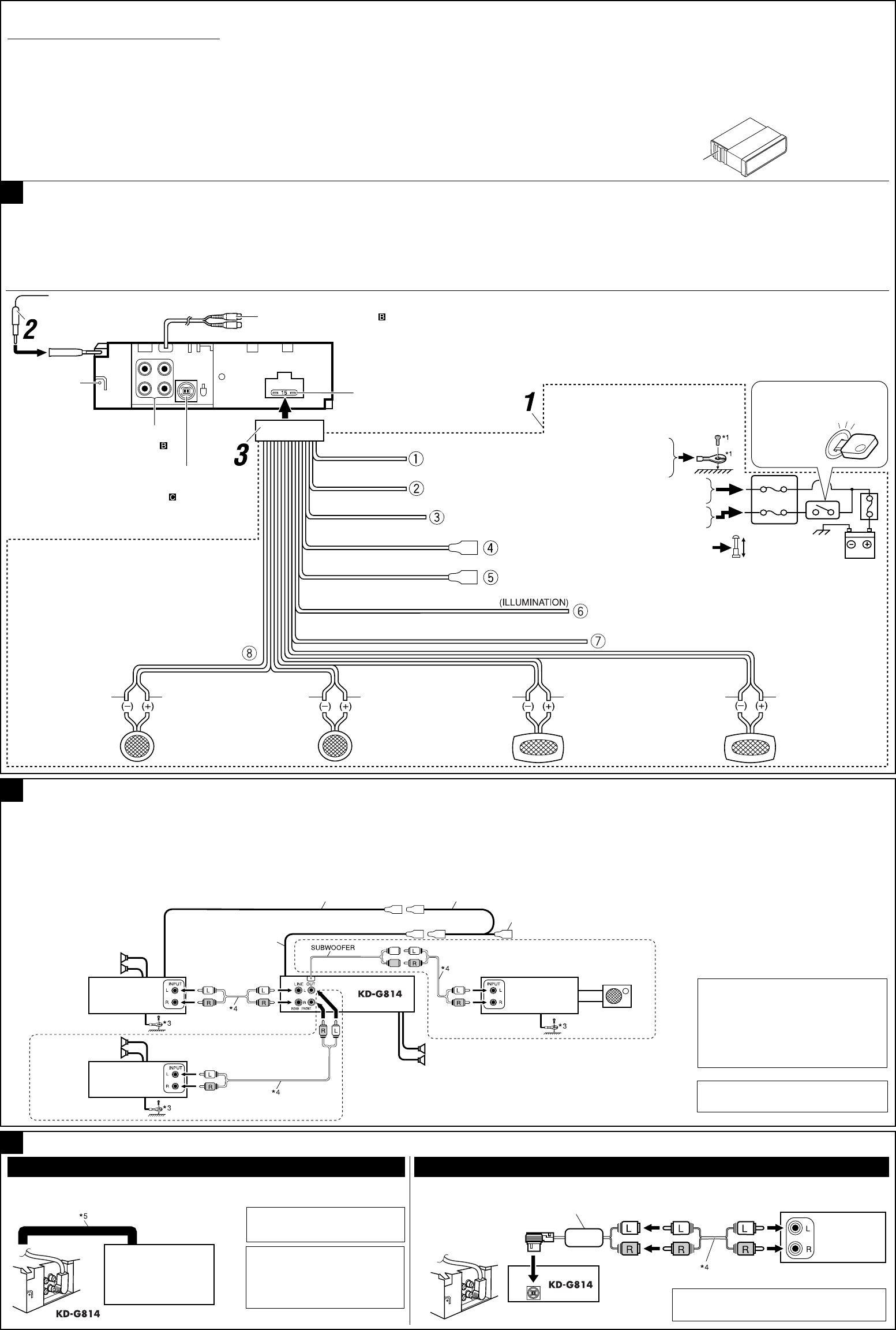
Typical connections
Before connecting: Check the wiring in the vehicle carefully. Incorrect connection may cause serious damage to this receiver.
The leads of the power cord and those of the connector from the car body may be different in color.
1 Connect the colored leads of the power cord in the order specifi ed in the illustration below.
2 Connect the antenna cord.
3 Finally connect the wiring harness to the receiver.
B
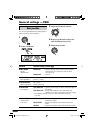
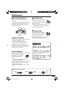
Connecting the external amplifi ers
You can connect amplifi ers to upgrade your car stereo system.
• Connect the remote lead (blue with white stripe) to the remote lead of the other equipment so that it can be controlled through this receiver.
• For amplifi er only:
– Disconnect the speakers from this receiver, connect them to the amplifi er. Leave the speaker leads of this receiver unused.
– The line output level of this receiver is kept high to maintain the hi-fi sounds reproduced from this receiver.
When connecting an external amplifi er to this receiver, turn down the gain control on the external amplifi er to obtain the best performance from this receiver.
Front speakers
Rear speakers
JVC Amplifi er
*
2
Before checking the operation of this receiver
prior to installation, this lead must be connected,
otherwise power cannot be turned on.
Line out (see
diagram )
Rear ground
terminal
15 A fuse
Black
Blue with white stripe
Red
Yellow
*
2
*
1
Not included for this receiver
To metallic body or chassis of the car
To a live terminal in the fuse block connecting to the car battery
(bypassing the ignition switch) (constant 12 V)
Ignition switch
Fuse block
To an accessory terminal in the fuse block
To the automatic antenna if any (250 mA max.)
Left speaker (front)
Right speaker (front)
Left speaker (rear) Right speaker (rear)
PurplePurple with black stripeGreenGreen with black stripeGrayGray with black stripeWhite
White with black stripe
To the remote lead of other equipment (200 mA max.)
Blue
To CD changer or another
external component (see
diagram
)
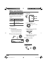
C Connecting other external components
CD changer
JVC CD changer
CAUTION
• Before connecting the CD
changer, make sure that the
receiver is turned off.
External component
KS-U57*
6
*
6
Line Input Adapter KS-U57 (not supplied
for this receiver)
External
component
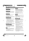
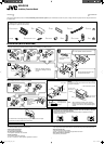
To prevent short circuits, we recommend that you disconnect the battery’s negative terminal and make all electrical connections before installing the receiver.
• Be sure to ground this receiver to the car’s chassis again after installation.
Notes:
• Replace the fuse with one of the specifi ed rating. If the fuse blows frequently, consult your JVC car audio dealer.
• It is recommended to connect to the speakers with maximum power of more than 50 W (both at the rear and at the front, with an impedance of 4 Ω to 8 Ω). If the maximum power is less than
50 W, change “AMP.GAIN” setting to prevent the speakers from being damaged (see page 21 of the INSTRUCTIONS).
• To prevent short-circuit, cover the terminals of the UNUSED leads with insulating tape.
• The heat sink becomes very hot after use. Be careful not to touch it when removing this receiver.
Heat sink
Brown
To cellular phone system
Orange with white stripe
To car light control switch
SUBWOOFER
(see diagram )
• Set “EXTERNAL IN” to “EXTERNAL IN” (See page 21 of the INSTRUCTIONS.)
• Set “EXTERNAL IN” to “CHANGER” (See page 21 of the INSTRUCTIONS.)
CD changer jack
*
5
Connecting cord supplied for
your CD changer
Remote lead
Y-connector (not supplied for this receiver)
Remote lead (Blue
with white stripe)
To the remote lead of other equipment or
automatic antenna if any
JVC Amplifi er
JVC Amplifi er
Front speakers
Subwoofer
*
3
Firmly attach the ground wire to the
metallic body or to the chassis of the
car—to the place not coated with
paint (if coated with paint, remove
the paint before attaching the wire).
Failure to do so may cause damage
to the receiver.
*
4
Signal cord (not supplied for this
receiver)
Instal1-2_KD-G814_002A_f.indd 2Instal1-2_KD-G814_002A_f.indd 2 1/27/05 11:35:26 AM1/27/05 11:35:26 AM