


4
Step
3
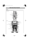
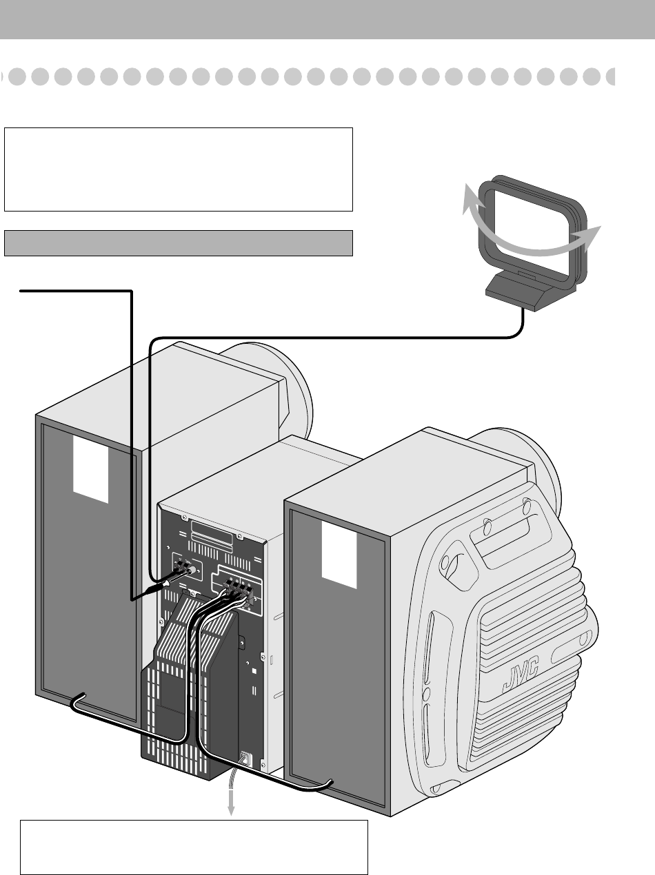
: Hook Up
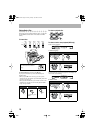
If you need more detailed information, see page 5.
T
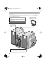
CATION: SPEAKER IMPEDANCE 6
Ω—16Ω
ANTENNA
RIGHT
MAIN
SPEAKERS
FM75W
COAXIAL
SUBWOOFERS
LEFT
AM
LOOP
AM EXT
Illustrations of the input/output terminals below are typical
examples.
When you connect other components, refer also to their manuals
since the terminal names actually printed on the rear vary among
the components.
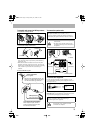
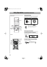
Turn the power off to all components before connections.
To a wall outlet
Plug the AC power cord only after all connections are complete.
• Demonstration will start automatically. To cancel it, see page 8.
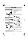
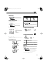
AM loop antenna (supplied)
Turn it until the best reception is
obtained.
FM antenna (supplied)
Extend it so that you
can obtain the best
reception.
HX-GX7.book Page 4 Friday,January 16, 2004 5:25 PM