


1
KD-PDR54
Installation/Connection Manual
GET0455-002A
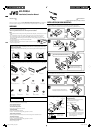
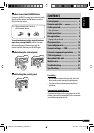
[UI]
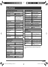
L
Handles
H
Washer (ø5)
I
Lock nut (M5)
J
Mounting bolt
(M5 × 20 mm)
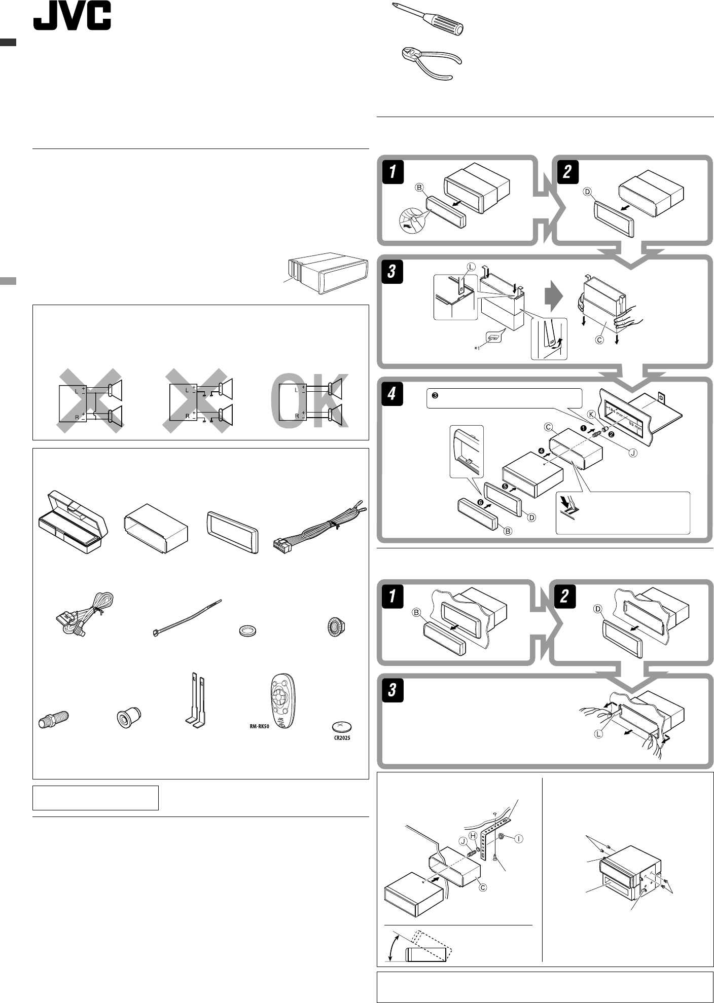
A / B
Hard case/Control panel
C
Sleeve
D
Trim plate
E
Power cord
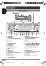
This unit is designed to operate on 12 V DC, NEGATIVE ground electrical systems. If your vehicle does
not have this system, a voltage inverter is required, which can be purchased at JVC car audio dealers.
Parts list for installation and connection
The following parts are provided for this unit. If any item is missing, consult your JVC car audio dealer
immediately.
M
Remote controller
N
Battery
1206DTSMDTJEIN
EN
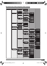
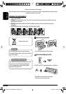
PRECAUTIONS on power supply and speaker connections:
• DO NOT connect the speaker leads of the power cord to the car battery; otherwise, the unit
will be seriously damaged.
• BEFORE connecting the speaker leads of the power cord to the speakers, check the speaker wiring in
your car.
© 2006 Victor Company of Japan, Limited
WARNINGS
To prevent short circuits, we recommend that you disconnect the battery’s negative terminal and make all
electrical connections before installing the unit.
• Be sure to ground this unit to the car’s chassis again after installation.
Notes:
• Replace the fuse with one of the specified rating. If the fuse blows frequently, consult your JVC car audio
dealer.
• It is recommended to connect to the speakers with maximum power of more than 50 W (both at
the rear and at the front, with an impedance of 4 Ω to 8 Ω). If the maximum power is less than
50 W, change “AMP GAIN” setting to prevent the speakers from being damaged (see page 14 of the
INSTRUCTIONS).
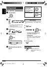
• To prevent short-circuit, cover the terminals of the UNUSED
leads with insulating tape.
• The heat sink becomes very hot after use. Be careful not to touch
it when removing this unit.
Heat sink
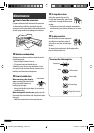
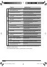
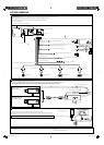
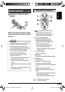
When using the optional stay
Note : When installing the unit on the mounting
bracket, make sure to use the 8 mm-long
screws. If longer screws are used, they
could damage the unit.
Bracket*
2
Pocket
Flat type screws (M5 × 8 mm)
*
2
Screw (option)
Stay (option)
Fire wall
Dashboard
Install the unit at an
angle of less than 30˚.
Removing the unit
Before removing the unit, release the rear section.
Insert the two handles, then pull them as
illustrated so that the unit can be removed.
Do the required electrical connections.
Bend the appropriate tabs to
hold the sleeve firmly in place.
INSTALLATION (IN-DASH MOUNTING)
The following illustration shows a typical installation. If you have any questions or require information
regarding installation kits, consult your JVC car audio dealer or a company supplying kits.
• If you are not sure how to install this unit correctly, have it installed by a qualified technician.
When installing the unit without
using the sleeve
In a Toyota car for example, first remove the car
radio and install the unit in its place.
*
1
When you stand the unit, be careful not to damage the fuse on the rear.
*
2
Not supplied for this unit.
F
Connection cable for iPod
K
Rubber cushion
Flat type screws
(M5 × 8 mm)
*
2
Bracket *
2
G
Cable tie
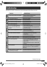
TROUBLESHOOTING
• The fuse blows.
* Are the red and black leads connected correctly?
• Power cannot be turned on.
* Is the yellow lead connected?
• No sound from the speakers.
* Is the speaker output lead short-circuited?
• Sound is distorted.
* Is the speaker output lead grounded?
* Are the “–” terminals of L and R speakers grounded in common?
• Noise interfere with sounds.
* Is the rear ground terminal connected to the car’s chassis using shorter and thicker cords?
• This unit becomes hot.
* Is the speaker output lead grounded?
* Are the “–” terminals of L and R speakers grounded in common?
• This unit does not work at all.
* Have you reset your unit?
Install1_KD-PDR54_002A_f.indd 1Install1_KD-PDR54_002A_f.indd 1 12/8/06 9:30:16 AM12/8/06 9:30:16 AM