


6
English
RIGHTLEFT
REAR CENTER
VOLTAGE
SELECTOR
110V
127V
220V
230V
-240V
ANTENNA
CD OPTICAL
DIGITAL
OUTPUT
AUX
AM EXT
FM
RIGHT
LEFT
IN
OUT
SUB WOOFER
OUT
FM
AM LOOP
(75 )
SPEAKERS
RIGHT
LEFT
VIDEO
OUT
CAUTION:
SPEAKER IMPEDANCE
6 ~ 16
STEREO RECEIVER
MODEL NO. MX - J777V
UNIT NO. MX-J777V
AC 110/127/220
/ 230 - 240V
50/6
0Hz 85W
CD OPTICAL
DIGITAL
OUTPUT
RIGHT LEFT
REAR CENTER
VOLTAGE
SELECTOR
110V
127V
220V
230V
-240V
ANTENNA
AUX
AM EXT
FM
RIGHT
LEFT
IN
OUT
SUB WOOFER
OUT
FM
AM LOOP
(75 )
SPEAKERS
RIGHT
LEFT
VIDEO
OUT
CAUTION:
SPEAKER IMPEDANCE
6 ~ 16
STEREO RECEIVER
MODEL NO. MX - J777V
UNIT NO. MX-J777V
AC 110/127/ 220
/ 230 - 240V
50/6
0Hz 85W
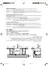
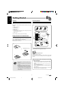
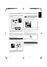
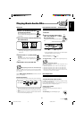
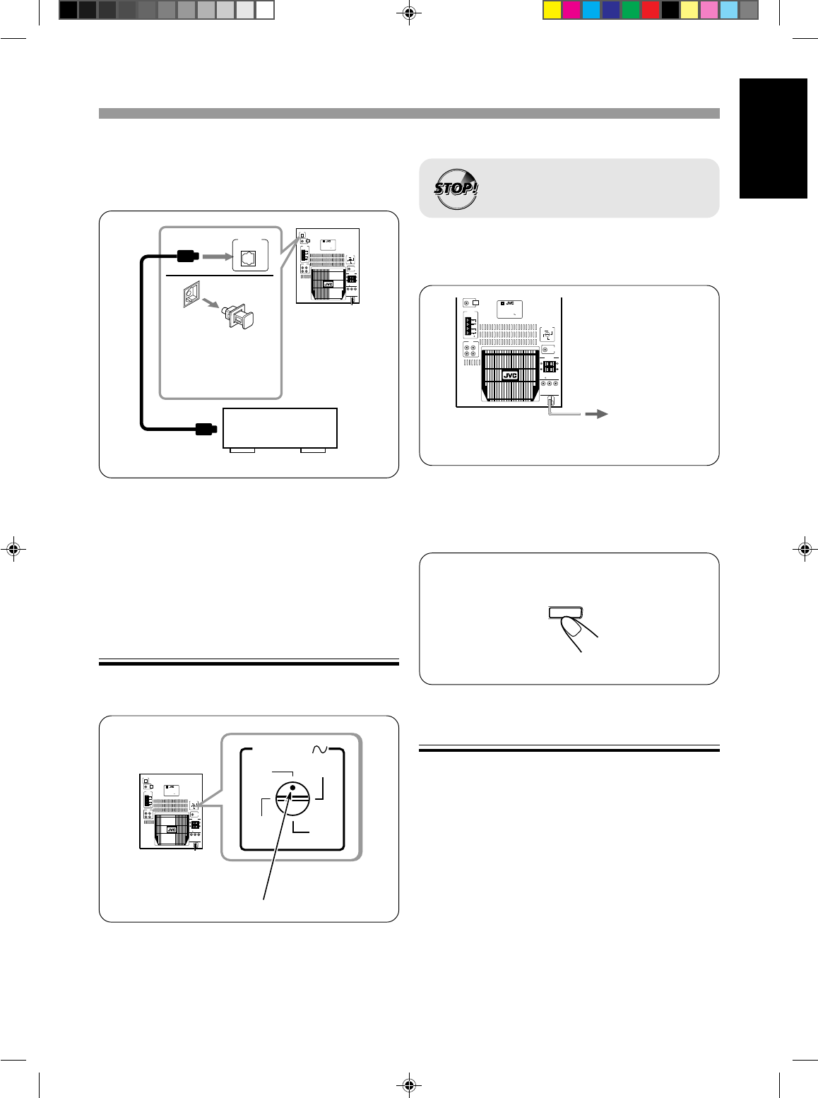
To connect audio equipment with an optical digital
input terminal
You can record CD sound onto the connected digital equipment.
Protective plug
Before connecting the
other equipment,
remove the protective
plug from the terminal.
Audio equipment with
an optical digital input
To optical
digital input
Connect an optical digital cord (not supplied) between the optical
digital input terminal on the other equipment and the CD OPTICAL
DIGITAL OUTPUT terminal.
CAUTION: CD OPTICAL DIGITAL OUTPUT can only be used
for playing or recording AUDIO CD. Noise might come out if you
play or record Video CD or SVCD. Disconnect optical digital cord
between other equipment and CD OPTICAL DIGITAL OUTPUT
terminal when playing or recording Video CD or SVCD.
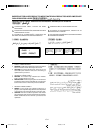
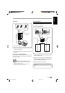
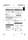
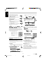
Adjusting the Voltage Selector
Before plugging in the unit, set the correct voltage for your area
with the voltage selector on the rear of the unit.
RIGHTLEFT
REAR CENTER
VOLTAGE
SELECTOR
110V
127V
220V
230V
-240V
ANTENNA
CD OPTICAL
DIGITAL
OUTPUT
AUX
AM EXT
FM
RIGHT
LEFT
IN
OUT
SUB WOOFER
OUT
FM
AM LOOP
(75 )
SPEAKERS
RIGHT
LEFT
VIDEO
OUT
CAUTION:
SPEAKER IMPEDANCE
6 ~ 16
STEREO RECEIVER
MODEL NO. MX - J777V
UNIT NO. MX-J777V
AC 110/127/220
/ 230 - 240V
50/6
0Hz 85W
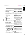
LINE VOLTS
110V
127V
220V
230V
-240V
Voltage mark
Use a screwdriver to rotate the voltage selector so the voltage number
the voltage mark is pointing at is the same as the voltage where you
are plugging in the unit.
• DO NOT plug in before setting the voltage
selector on the rear of the unit and all
connection procedures are complete.
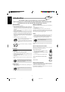
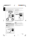
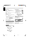
NOW, you can plug in the unit and other connected
equipment FINALLY!
To a wall outlet
If the wall outlet does not match the AC plug, use the supplied
AC plug adaptor.
When connecting the AC power cord into a wall outlet, the unit
automatically starts display demonstration.
To stop the display demonstration, press any button on the unit or
the remote control.
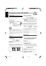
To start the display demonstration manually
Press and hold DEMO / for more than 2 seconds.
To stop the demonstration, press any button.
CANCEL
DEMO
• DO NOT plug in before setting the voltage
selector on the rear of the unit and all
connection procedures are complete.
To know the locations of Buttons and controls
Please refer to page 30, 31 and 32 for location of the buttons and
controls on your unit. The buttons and controls mentioned in the
steps in this manual have been inserted with numbers i.e 1, 2 (for
unit) or 1, 2 ( for remocon) for your easy reference.
EN6-17;MX-J777V/PM6 7/8/99, 9:16 AM6