


SERVICING YOUR JL AUDIO AMPLIFIER
If your amplifier fails or malfunctions, please
return it to your authorized JL Audio dealer so
that it may be sent in to JL Audio for service.
There are no user serviceable parts or fuses
inside the amplifier.The unique nature of the
circuitry in the JL Audio amplifiers requires
specifically trained service personnel. Do not
attempt to service the amplifier yourself or
through unauthorized repair facilities.This will not
only void the warranty, but may result in the
creation of more problems within the amplifier.
If you have any questions about the installation or
setup of the amplifier not covered in
this manual, please contact your dealer or the
JL AUDIO Technical Department for assistance:
(954) 443-1100
9:00 AM – 5:30 PM Eastern Time,
Monday – Friday
JL AUDIO 500/5 13
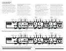
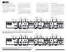
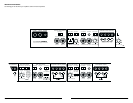
that channel pair.This requires an RCA “Y-adaptor”
(not included.) Connection of only one RCA input
will result in reduced power output, increased
distortion and can cause the amplifier to overheat.
Do not do this! Instead, use a “Y-adaptor” to split
the mono signal into both left and right RCA inputs.
Why a mono signal? If you are bridging a pair of
channels and use a stereo input, the only
information that will reach the amplifier stage is the
common-phase portion of the signal.This may be
useful for passively deriving a center-channel signal,
but is not going to give you a defined left or right
channel. If you are looking to reproduce a single
channel’s signal, you must split the mono signal with
a “Y-adaptor” and connect it to both left and right
RCA inputs for the bridged channel pair.
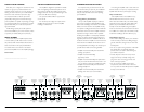
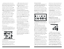
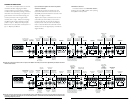
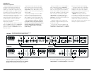
STATUS INDICATOR LIGHTS /
PROTECTION CIRCUITRY
There are three status indicator lights on the top
of the amplifier. These are as follows:
1) “Power” (Green): lights to indicate that the
amplifier is turned on and operating normally.
2) “Thermal” (Red): lights to indicate that the
amplifier has exceeded its safe operating
temperature, putting the amplifier into a self-
protection mode, which reduces the power output
of the amplifier. The red light will shut off and the
amplifier will return to normal, full-power operating
mode if the heat sink temperature drops back to a
safe level.
3) “Low Ω” (Amber): lights to indicate that the
impedance of the speaker load connected to the
amplifier is lower than the optimum load impedance
range for the amplifier.When this light is on, a
protection circuit engages and reduces the power
output of the front or subwoofer channel,
depending on which channel is experiencing the
problem.The amber indicator will also light when a
short-circuit is detected in the speaker wiring (this
can be a short between the positive and negative
speaker wires or between either speaker wire and
the vehicle chassis).This can be used to diagnose a
short-circuit by only connecting one of the amplifier
sections at a time (front, rear and subwoofer).
The amber LED will light when you connect the
section that is experiencing the problem and turn
the volume up.
There is only one condition that will shut
down an undamaged 500/5 completely…
If battery voltage drops below 10 volts, the entire
amplifier will shut itself off.The green “Power”
indicator on the top of the amplifier will turn off
when this occurs.The amplifier will turn back on
when voltage climbs back above 10 volts.This may
happen in a rapid cycle when bass-heavy program
material causes a weak charging system to dip
below 10 volts momentarily. If this is happening in
your system, have your charging system inspected to
make sure it is working properly.A 0.5 or 1.0 Farad
rapid-discharge capacitor connected in parallel to
the amplifier power connections will minimize these
short duration voltage dips in most systems that are
having this problem.
For information on troubleshooting this
amplifier, refer to Appendix D (page 26).
12 JL AUDIO 500/5