


any amplifier in the system beyond the maximum
level established during the procedure outlined in
Appendix B (page 22). Doing so will result in
audible distortion and possible speaker damage.
Be aware that all three “Input Sens.”
adjustments will have to be made, regardless of
how many input cables are feeding the amplifier.
These controls will allow you to set the
appropriate relative levels for the Front, Rear and
Subwoofer Channels.
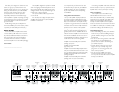
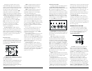
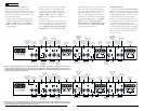
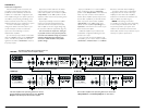
Subwoofer “Input From” Selection:
Located to the left of the “Input Voltage” switch
in the “Subwoofer Channel Control Section” is a
switch labeled “Input From”.This switch
determines whether the subwoofer channel will
receive its input from the “Independent Sub Input”
jacks (select “Ind.”) or from a sum of the Front and
Rear Channel Input signals (select “F+R”) or from
the Front Channel Inputs only (select “Front”).
Front and Rear Channel “Input Mode” Selection:
Located to the right of the rear channel input
jacks in the “Rear Input Section” is a switch
labeled “F/R Input Mode”.This switch determines
whether the front and rear channels will receive
their input independently (select “4ch”) or from
the “Rear Input Section” jacks only (select “2ch”).
CROSSOVER CONTROLS
Crossovers are groups of individual electronic filters
which allow only certain frequency ranges to pass
through them by attenuating frequencies outside
the selected range.These filters allow the user to
specify what frequency range will be sent out of
each channel section of the amplifier.This, in turn,
allows each speaker system to only reproduce a
range of frequencies it is well-suited for,resulting in
reduced distortion and improved fidelity.
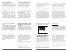
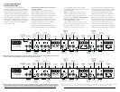
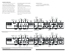
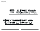
Front Filter Section:
1) “Filter Mode” Control: Located in the“Front
Filter Section”, this switch allows you to configure
the Front Channel filter into one of three modes:
“Off” (Defeated): Defeats the filter for the Front
Channels completely, allowing the full range of
frequencies present at the inputs to feed that pair
of channels.This is useful for systems utilizing
outboard crossovers or requiring full-range
reproduction from these channels.
“BP” (Bandpass): Configures the Front Channel
Filter to attenuate frequencies above the selected
filter frequency and below the frequency selected in
the Rear Channel High-Pass Filter. This creates a
true bandpass filter well-suited for driving mid-bass
or mid-range speakers in a tri-amplified system (see
page 18 for details).
“HP” (High-Pass):Configures the Front Channel
Filter to attenuate frequencies below the selected filter
frequency. Useful for connection of component
speakers to the front channels in a bi-amplified system.
2) “Filter Slope” Control:This switch allows you
to select from two filter slopes.
“12dB”: Configures the Front Channel Filter to
attenuate frequencies below the selected filter
frequency at a rate of 12 dB per octave
(Butterworth alignment).
“24dB”: Configures the Front Channel Filter to
attenuate frequencies below the selected filter
frequency at a rate of 24 dB per octave (Linkwitz-
Riley alignment).
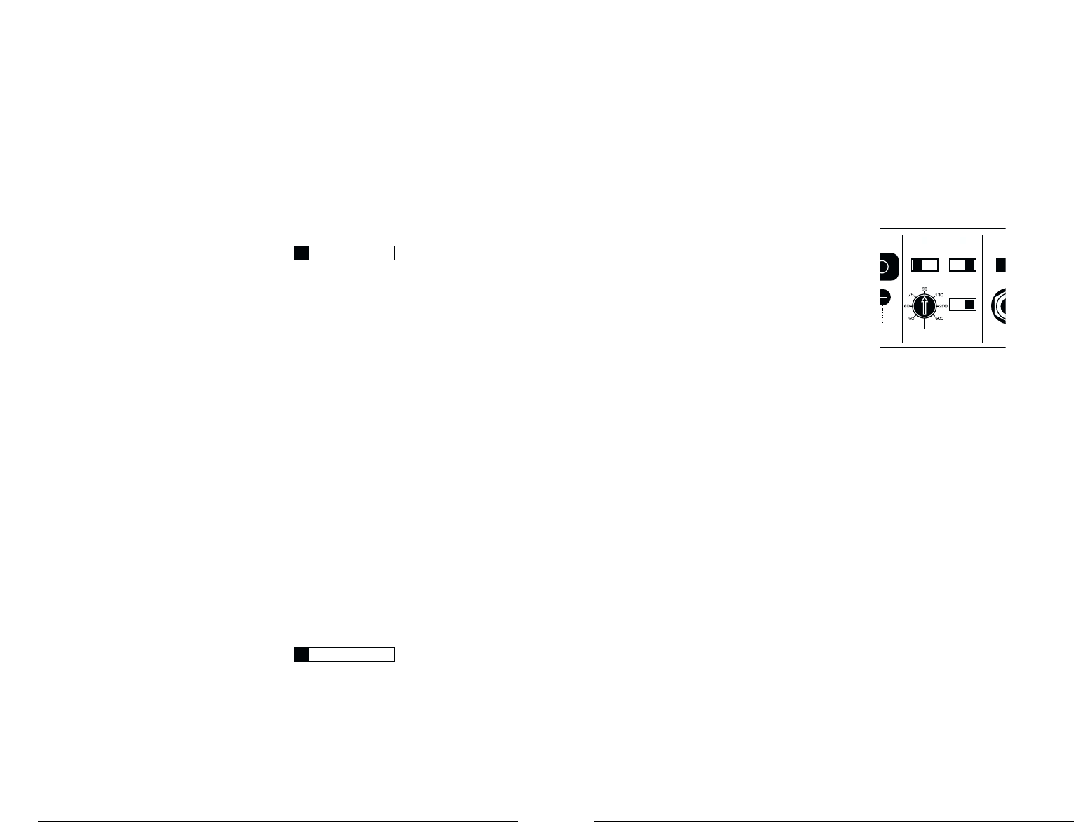
Fro
Input
Low
Le
Front Filter Section
Freq. Range
x1/x10
HP Filter Freq.(Hz)
Filter Slope
12dB/24dB
Filter Mode
Off/BP/HP
5Wx2)
JL AUDIO 500/5 7
TURN-ON LEAD
The 500/5 uses a conventional +12V remote
turn-on lead, typically controlled by the source unit's
remote turn-on output.The amplifier will turn on
when +12V is present at its “Remote” input and
turn off when +12V is switched off. If a source unit
does not have a dedicated remote turn-on output,
the amplifier’s turn-on lead can be connected to
+12V via a switch that derives power from an
ignition-switched circuit.
The 500/5's “Remote” turn-on connector is
designed to accept 18 AWG – 8 AWG wire.12
AWG is more than adequate for this purpose.
To connect the remote turn-on wire to the
amplifier, first back out the set screw on the top of
the amplifier, using the supplied hex wrench. Strip
1/2 inch (12mm) of wire and insert the bare wire
into the receptacle on the front panel of the
amplifier, seating it firmly so that no bare wire is
exposed.When using smaller wire, it may be
necessary to strip 1 inch of insulation from the wire
and fold the bare wire in half prior to insertion.
While holding the wire in the terminal, tighten the
set screw firmly, taking care not to strip the head of
the screw and making sure that the wire is firmly
gripped by the set screw.
INPUT SECTIONS
Three left/right pairs of RCA type jacks are
provided for input (one pair for the subwoofer
channel, one pair for the rear channels and one pair
for the front channels).There are several ways that
the 500/5's inputs can be configured. Please read the
“System Configurations” section of this manual (page
14) carefully to determine the proper configuration
for your application.
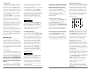
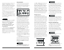
Input Voltage Range:
A wide range of signal input voltages can be
accommodated by each of the 500/5's input stages
(200mV – 8V).This wide range is split up into two
sub-ranges, accessible via switches located in each
input section of the amplifier. Be aware that
each input section's “Input Voltage” switch
will have to be configured, regardless of
how many inputs are actually feeding the
amplifier.
The “Low” position on each “Input Voltage”
switch selects an input sensitivity range between
200mV and 2V.This means that the Input Sensitivity
rotary control will operate within that window. If
you are using an aftermarket source unit, with
conventional preamp-level outputs, this is most likely
the position that you will use.
The “High” position on each “Input Voltage”
switch selects an input sensitivity range between
800mV and 8V.This is useful for certain high-output
preamp level signals as well as speaker-level output
from source units and small amplifiers.To use
speaker-level sources, splice the speaker output
wires of the source unit or small amplifier onto a
pair of RCA plugs.
The output of the amplifier will decrease for a
given input voltage when the “Input Range” switch
is placed in the “High” position. Conversely, the
output will be higher with the switch in the “Low”
position.While this may sound counter-intuitive, it is
consistent with the descriptions above.
Input Sensitivity Adjustment:
Located next to the “Input Voltage” switch in
each input section is a rotary control labeled “Input
Sens.” Once the appropriate “Input Voltage” range
has been selected, this control can be used to
match up the signal level of the system to produce
the desired level from the amplifier. Rotating the
control clockwise will result in higher sensitivity
(louder for a given input voltage). Rotating the
control counter-clockwise will result in lower
sensitivity (quieter for a given input voltage.) Be
aware that each of the three “Input Sens.”
adjustments will have to be made, regardless of
how many inputs are feeding the amplifier.These
controls will allow you to set the appropriate
relative levels for the subwoofer channels and the
front and rear channels.
To properly set each set of amplifier channels
for maximum clean output, please refer to
Appendix B (page 22) in this manual.After using
this procedure, you can then adjust the relative
level of each channel pair by adjusting the input
sensitivity downward on either or both channel
pairs,if they require attenuation to achieve the
desired system balance.
Do not increase the “Input Sens.” setting for
IMPORTANT
!
IMPORTANT
!
6 JL AUDIO 500/5