


12) Carefully review the amplifier’s control
settings to make sure that they are set according to
the needs of the system.
13) Install power wire fuse (50A for a
single 500/5) and reconnect the negative
battery post terminal.
14) Turn on the source unit at a low level
to double-check that the amplifier is configured
correctly.Resist the temptation to crank it up until
you have verified the control settings.
15) Make necessary adjustments to the input
sensitivity controls of the subwoofer channel and
front and rear channel pairs to obtain the right
overall output and the desired balance between
their outputs. See Appendix B (page 22) for the
recommended input sensitivity setting method.
16) Enjoy the fruits of your labor with your
favorite music.
POWER CONNECTIONS
Before installing the amplifier, disconnect the
negative (ground) wire from the vehicle's battery.
This will prevent accidental damage to the system,
the vehicle and your body during installation.
The 500/5's “+12 VDC” and “Ground”
connections are designed to accept 4 AWG power
wire. 4 AWG is the only recommended
power wire size for this amplifier.
If you are installing the 500/5 with other
amplifiers and wish to use a single main power wire,
use 2 AWG or 1/0 AWG main power wire
(depending on the overall current demands of all
the amplifiers in the system).This 2 AWG or 1/0
AWG power wire should terminate into a
distribution block mounted as close to the amplifiers
as possible and should connect to the 500/5 with
4 AWGpower wire.
Please note that smaller AWG numbers mean
bigger wire and vice-versa (1/0 AWG is biggest, 2
AWG is smaller,then 4 AWG, then 8 AWG,etc.).
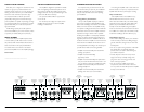
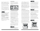
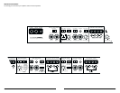
JL AUDIO 500/5
five-channel system amplifier
+12VDC Ground Remote
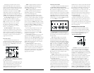
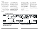
To connect the power wires to the amplifier,first
back out the set screw on the top of the amplifier,
using the supplied 2.5 mm hex wrench. Strip
1/2 inch (12 mm) of insulation from the end of
each wire and insert the bare wire into the
receptacle on the front panel of the amplifier, seating
it firmly so that no bare wire is exposed.While
holding the wire in place, tighten the set screw
firmly,taking care not to strip the head of the screw.
The ground connection should be made using
the same gauge wire as the power connection
(4 AWG) and should be kept as short as possible,
while accessing a solid piece of sheet metal in the
vehicle.The surface of the sheet metal should be
sanded at the contact point to create a clean, metal-
to-metal connection between the chassis and the
termination of the ground wire.The use of a star
washer to lock down the connection is advisable.
Any wires run through metal barriers (such as
firewalls), must be protected with a high quality
rubber grommet to prevent damage to the
insulation of the wire. Failure to do so may result in
a dangerous short circuit.
Many vehicles employ small (10 AWG - 6 AWG)
wire to ground the battery to the vehicle chassis and
to connect the alternator's positive connection to the
battery.To prevent voltage drops,these wires should
be upgraded to 4 AWG when installing amplifier
systems with main fuse ratings above 60A.
FUSE REQUIREMENTS
It is absolutely vital that the main power wire(s)
to the amplifier(s) in the system be fused within
18 inches (45 cm) of the positive battery post
connection.The fuse value at each power wire
should be high enough for all of the equipment
being run from that power wire. If only the
500/5 is being run from that power wire, we
recommend a 50A fuse be used.AGU (big glass
fuse) or MaxiFuse™ (big plastic-body fuse) types
are recommended.
No fuse is required or recommended directly
before the amplifier power connection. If one is
desired, we recommend the use of a 50A AGU fuse
or MaxiFuse™ type.
IMPORTANT
!
JL AUDIO 500/5 5
PRODUCT DESCRIPTION
The JL Audio 500/5 is a five-channel system
amplifier utilizing patented Absolute Symmetry™
Class AB technology for its front and rear channels
and patented Class D technology for its subwoofer
channel. Front and subwoofer channels benefit from
JL Audio's exclusive R.I.P.S. power supply design
which optimizes the output of each section for any
impedance between 1.5 and 4 ohms per channel.
The staggered power distribution of the front
and rear channel pairs (100W x 2 for front and
25 x 2 for rear) allows for a wide variety of
application options.The 500/5 can be operated in
the following modes:
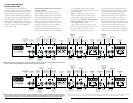
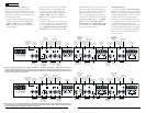
1) As a full-system amplifier in bi-amp mode with
its subwoofer channel driving subwoofers in low-
pass mode (250W x 1), front channels driving front
component speakers (100W x 2) in high-pass
mode and rear channels driving rear component
speakers in high-pass mode (25W x 2).
2) As a full-system amplifier in a tri-amplified
system, delivering band-passed signals through its
front channels to mid-bass/mid-range speakers and
high-passed signals through its front channels to
tweeters.
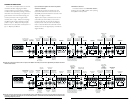
The 500/5's flexible input and crossover sections
permit operation with a wide variety of source units
and system configurations.The 500/5 can operate
with a single pair of stereo inputs or with separate
inputs for front and rear channel pairs, if the source
unit is equipped with front and rear outputs.The
subwoofer channel can be driven with a discrete
signal from a source unit’s subwoofer output or can
receive its signal from the front and/or rear channel
inputs.
The 500/5's preamp output can send pass-
through signals from the front inputs only,the
subwoofer inputs only OR a sum of the front and
rear input signals.This allows the connection of
additional subwoofer amplifier(s) or full-range
amplifiers.
TYPICAL INSTALLATION SEQUENCE
The following represents the sequence for a
typical amplifier installation, using an aftermarket
source unit. Additional steps and different
procedures may be required in some applications.
If you have any questions, please contact your
authorized JLAudio dealer for assistance.
1) Disconnect the negative battery post
connection and secure the disconnected cable to
prevent accidental re-connection during installation.
This step is not optional!
2) Run power wire (minimum 4 AWG) from
the battery location to the amplifier mounting
location, taking care to route it in such a way that
it will not be damaged and will not interfere with
vehicle operation. Use 2 AWG or 1/0 AWG
power wire if additional amplifiers are being
installed with the 500/5.
3) Connect power wire to the positive battery
post. Fuse the wire with an appropriate fuse block
(and connectors) within 18 inches (45 cm) wire
length of the positive battery post.This fuse is
essential to protect the vehicle. Do not install the
fuse until the power wire has been connected to
the amplifier.
4) Run signal cables (RCA cables) and remote
turn-on wire from the source unit to the amplifier
mounting location.There are several ways to provide
input to the 500/5. Please read the rest of this manual
carefully to choose the best one for your system.
5) Run speaker wire from the speaker systems to
the amplifier mounting location.
6) Find a good, solid metal grounding point close
to the amplifier and connect the negative power wire
to it using appropriate hardware.Use 4 AWG power
wire, no longer than 36 inches (90 cm) from the
amplifier to the ground connection point. In some
vehicles, it may be necessary to upgrade the battery
ground wire. (See page 5 for important notice).
7) Securely mount the amplifier using the
supplied screws.
8) Connect the positive and negative power
wires to the amplifier. A fuse near the amplifier is
not necessary.
9) Connect the remote turn-on wire
to the amplifier.
10) Connect the RCA input cables
to the amplifier.
11) Connect the speaker wires to the amplifier.
4 JL AUDIO 500/5