


Subwoofer Channel Filter:
The 500/5's subwoofer channel filter (located in
the “Subwoofer Channel Control Section”
employs an advanced state-variable, low-pass active
filter. This feature is designed to attenuate
frequencies above its filter frequency, so that the
system's subwoofers do not reproduce any audible
midrange content.The low-pass filter in the 500/5 is
fully variable between 40 Hz and 200 Hz via the
“Filter Freq.” control knob and features the ability
to select between a moderate “12dB” per octave
or a steep “24dB” per octave slope.
1) “Sub LP Filter”: This switch, located in the
Subwoofer Channel Control Section, configures the
low-pass filter for the subwoofer channel into one
of three modes.
“Off”: Defeats the filter for the subwoofer
channels completely, allowing the full range of
frequencies present at the input to feed the sub
channel.This is useful for systems utilizing outboard
crossovers. Keep in mind that defeating the “Sub LP
Filter” also defeats the “LF Boost” and “Infrasonic
Filter”.With the “Sub LP Filter”defeated (“Off”), the
subwoofer channel's upper frequency response limit
is 500 Hz, due to its bass-specific Class D design.
“12dB”: Configures the filter for the subwoofer
channel to attenuate frequencies above the selected
filter frequency at a rate of 12 dB per octave
(Butterworth alignment).
“24dB”: Configures the filter for the subwoofer
channel to attenuate frequencies above the selected
filter frequency at a rate of 24 dB per octave
(Linkwitz-Riley alignment).
Depending on the subwoofer system and the
vehicle, different slopes may be required to produce
a smooth transition to the midbass speakers in the
system. Experiment to find the slope which best
matches the acoustic requirements of your system.
Hint: A trunk mounted sub whose output has to
“fight” through a rear deck or a back seat often
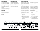
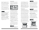
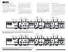
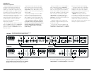
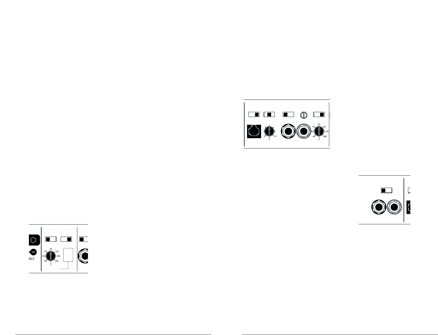
Subwoofer Channel Control Section
Input Sens.
Input Voltage
Low/High
Independent Sub Input
Sub LP Filter
Off/12dB/24dB
Filter Freq. (Hz)
Remote Bass
Port
Off/30Hz
LF Boost (dB)
Input From:
Ind./F+R/Front
Infrasonic Filter
Left
Right
+1
+13
+3
+7
+10
benefits from the 12 dB per octave slope which lets
more upper bass content pass through.A sub that
fires directly into the listening environment is more
likely to benefit from a 24 dB per octave slope.
The above hint is not a “set-in-stone” rule…You
should always listen to the system carefully to
determine the best choice as vehicle acoustics and
other factors play a big role in choosing the most
appropriate filter slope.
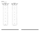
2) “Filter Freq. (Hz)” The filter frequency
markings surrounding this rotary control are for
reference purposes and are generally accurate to
within 1/3 octave or better. If you would like to
select the filter cutoff frequency with a higher level
of precision, consult “Chart A2” in Appendix A of
this manual (page 20).
PREAMP OUTPUT SECTION
The 500/5 incorporates a flexible preamp
output section, permitting additional amplifiers
to be added to the system.This pre-amp output
can be configured three different ways using
the switch labeled “Signal From” in the
“Preamp Output Section”.
1) “Sub LP”: The preamp output delivers the
same mono-summed signal that is feeding the
500/5's subwoofer channel when the “Sub LP”
mode is engaged, including all the low-pass filtering,
“LF Boost” and “Infrasonic Filter”processing that is
selected. This mode is useful for feeding an
additional (slave) subwoofer amplifier (the JLAudio
250/1 matches the 500/5’s subwoofer channel
perfectly). For more information on adding
additional subwoofer amplifiers in master / slave
mode, please refer to Appendix C on page 24.
2) “F+R Inputs” (Front + Rear):This is a pass-
through mode for the preamp output, delivering a
sum of the signals being fed to the “Front Input
Section” and “Rear Input Section” of the amplifier
(If the input signal is full-range, the preamp output
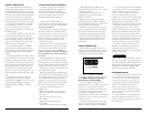
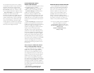
Sub LP/F+R Inputs/Front
Preamp Output Section
Signal From
Rem
Of
Infras
Left Ch.
Right Ch.
JL AUDIO 500/5 9
Depending on the speaker system and the
vehicle, different filter slopes may be required to
produce a smooth transition between the sound of
different speakers in the system. Experiment to find
the slope which best matches the acoustic
requirements of the system.The sharper “24dB”
setting will do a better job of protecting small
speakers with limited power handling.The shallower
“12dB” octave setting allows the front speakers to
reproduce more content below the cutoff frequency.
3) “Freq. Range” Control: When thrown to
the right, this switch multiplies the cutoff
frequency selected by the rotary “Filter Freq.
(Hz)” control by a factor of 10. In the “x1”
position, the range of the rotary control is
50 - 500 Hz (as marked). In the “x10”
position, the range of the rotary control is
500 Hz - 5 kHz (5000 Hz).
4) “Filter Freq. (Hz)”The filter frequency
markings surrounding this rotary control are for
reference purposes and are generally accurate to
within 1/3 octave or better. If you would like to
select the filter cutoff frequency with a higher level
of precision, consult the charts in Appendix A
(page 20) of this manual.
Rear Filter Section:
The rear channels of the 500/5 can be
operated through the amplifier's built-in rear high-
pass filter.This attenuates frequencies below the
one selected by the “Filter Freq.” control in the
Rear Filter Section.
1) “High-Pass Filter” Control:This switch allows
you to defeat the Rear Channel Filter or select from
two different filter slopes.
“Off”: Defeats the filter completely, allowing the full
range of frequencies present at the inputs to feed
that pair of channels.This is useful for systems
utilizing outboard crossovers or requiring full-range
reproduction from these channels.
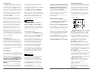
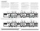
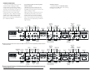
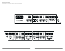
Input Volta
Low/Hig
Left C
Rear Filter Section
Freq. Range
x1/x10
Filter Freq. (Hz)
High-Pass Filter
Off/12dB/24dB
50Wx1)
Also sets
low-pass
cutoff for
Front Ch.
Bandpass
filter (when
selected)
“12dB”: Configures the filter for that pair of
channels to attenuate frequencies below the
selected filter frequency at a rate of 12dB per
octave (Butterworth alignment).
“24dB”: Configures the filter for that pair of
channels to attenuate frequencies below the
selected filter frequency at a rate of 24dB per
octave (Linkwitz-Riley alignment).
Depending on the speaker system and the
vehicle, different filter slopes may be required to
produce a smooth transition between the speakers
in the system. Experiment to find the slope which
best matches the acoustic requirements of your
system.The sharper “24dB” setting will do a better
job of protecting small speakers with limited power
handling.The shallower “12dB” octave setting
allows the rear speakers to reproduce more low-
frequency content.
If you are using the 500/5 in tri-amp mode,
these rear filter controls will determine the
tweeter crossover frequency and slope.We
recommend that you use the sharper “24dB”
position for most tweeters.
2) “Freq. Range” Control: When thrown to the
right, this switch multiplies the cutoff frequency
selected by the rotary“Filter Freq. (Hz)” control by
a factor of 10. In the “x1” position, the range of the
rotary control is 50 - 500 Hz (as marked). In the
“x10” position, the range of the rotary control is
500 Hz - 5 kHz (5000 Hz).
3) “Filter Freq. (Hz)”The filter frequency
markings surrounding this rotary control are for
reference purposes and are generally accurate to
within 1/3 octave or better. If you would like to
select the filter cutoff frequency with a higher level
of precision, consult “Chart A1” in Appendix A
(page 20) of this manual.
8 JL AUDIO 500/5