10 | JL Audio - 1000/1v2 Owner’s Manual
11
SUBWOOFER OUTPUT
The 1000/1v2 employs JL Audio’s exclusive
Regulated, Intelligent Power Supply (R.I.P.S.)
design. This sophisticated power supply
allows the amplifier to produce its optimum
power (1000 watts x 1) over a wide range of
speaker impedances.
Subwoofer Output
MONO OUTPUT ONLY
Output Polarity
Normal
|
Reversed
Unlike conventional amplifiers that require
a specific impedance to produce optimum
power, the R.I.P.S.-equipped 1000/1v2 gives
you the freedom to use a variety of subwoofer
configurations that achieve final nominal
impedances between
1.5 – 4Ω (without sacrificing power output or
sound quality).
The operation of the R.I.P.S. circuitry is
entirely automatic and adjusts itself every time
the amplifier is turned on according to the lowest
impedance present at the speaker load. There are
no user controls to configure. The system
operates through multiple stages of impedance
PQUJNJ[BUJPODIPPTJOHUIFTUBHFNPTUBQQSPQSJBUF
to the actual impedance of the speaker(s) you
connect to it.
IMPORTANT
!
If you connect a load higher than 4Ω nominal
to the 1000/1v2, power will drop by half with
every doubling of impedance above 4Ω. If you
connect a load lower than 1.5Ω nominal to the
1000/1v2, the amplifier protection circuitry
activates a “safe” mode which reduces amplifier
power to protect the circuitry from failure (the
yellow LED on the top of the amplifier will
light to indicate that this has happened). See
page 12 for details.
IMPORTANT
!
Speaker loads below 1.5Ω nominal are not
recommended and may cause the amplifier
output to distort excessively.
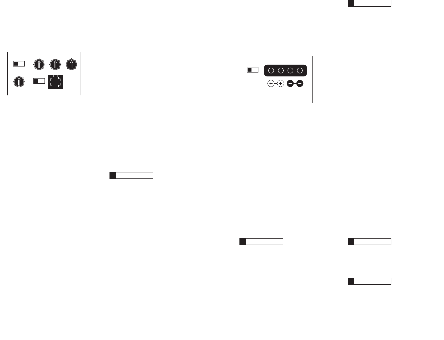
Speaker connections to the 1000/1v2 are
straightforward and take place at the far right of
the front panel. You will notice that there are two
i+wQPTJUJWFDPOOFDUJPOTBOEUXPi–wOFHBUJWF
connections. This is to facilitate multiple speaker
wiring. The two positive and two negative
connections are connected in parallel inside
the amplifier. Connecting two speakers, each to
one set of positive and negative terminals, will
result in a parallel speaker connection. If only
connecting one pair of speaker wires, it is not
necessary to use both sets of connections.
%POPUDIBTTJTHSPVOEBOZTQFBLFSTDPOOFDUFE
UPUIJTPSBOZPUIFS+-"VEJPBNQMJGJFS%PJOHTP
will cause the amplifier to go into protection and
mute the output.
The 1000/1v2’s speaker connectors are
designed to accept 12 AWG – 8 AWG wire.
To connect the speaker wires to the amplifier,
first back out the set screws on the top of the
amplifier, using the supplied 2.5 mm hex
wrench. Strip 1/2 inch (12 mm) of insulation
from each wire and insert the bare wire end
into the receptacles on the front panel of the
amplifier, seating them firmly so that no bare
wire is exposed. While holding each wire in place,
tighten each set screw firmly, taking care not to
strip the head of the screw and making sure that
the wire is firmly gripped by the set screw.
IMPORTANT
!
Do NOT attempt to “bridge” two 1000/1v2’s or
combine their output to a single load in any
manner. Doing so will damage the amplifier(s).
IMPORTANT
!
Before reconnecting the battery ground and
turning the system on, verify that all control
settings on the amplifier are set according to
the needs of the system.
ADVANCED BASS CONTROL SECTION
The 1000/1v2 includes a versatile bass
processing section consisting of two
primary components: a fully variable,
24 dB per octave infrasonic filter and a
QBSBNFUSJDTJOHMFCBOEFRVBMJ[FS
Infrasonic Filter “Q” Center Freq. Boost (dB)
Advanced
Bass
Control
Infrasonic Freq. (Hz) Remote Bass Port
Mode
Bass EQ
Off
|
On
Off
|
On
15
18
25
30
40
50
60
0.5
0.7
1.1
1.6
2.7
4.3
20
25
35
45
55
70
80 0
+4
+10
+13
+15
1) “Infrasonic Filter”: The infrasonic filter is a
24 dB/octave high-pass filter, with a fully
WBSJBCMFDVUPGGGSFRVFODZCFUXFFO)[
8IFOTFUBUGSFRVFODJFTMPXFSUIBO)[JU
conserves amplifier power without audibly
affecting the quality of the sub-bass output. If
TFUBUGSFRVFODJFTIJHIFSUIBU)[UIFSFXJMM
be an audible effect, but one which may be
desirable for SPL competition purposes or curve
shaping of a bottom-heavy system. With ported
enclosures, the use of the infrasonic filter is
highly recommended to protect the speaker(s)
from excessive excursion below box tuning.
With sealed enclosures, the use of the filter is
less necessary, but can still help protect the
speaker system. If you would like to select the
infrasonic filter frequency with a higher level of
precision, consult Appendix C: Chart A-3 (page
17) of this manual. The infrasonic filter can be
DPNQMFUFMZEFGFBUFECZTFMFDUJOHUIFiOffw
QPTJUJPOPOUIFiModewTXJUDI5IJTCZQBTTFT
all signal from flowing through the circuit.
2) Parametric Bass Equalizer: The parametric
FRVBMJ[FSBMMPXTUIFVTFSUPTFMFDUUIFDFOUFS
frequency of the boost band as well as the
CBOEXJEUIiQwPGUIFCPPTUCBOE5IFiQ"
control selects the bandwidth of the boost
around the center frequency. Lower numbers
pertain to wider bandwidths while higher
number pertain to narrower bandwidths.
5IFiCenter FreqwDPOUSPMTFMFDUTUIFDFOUFS
frequency of the boost bandwidth within
BSBOHFPG)[*GZPVXPVMEMJLFUP
select the filter frequency with a higher level
of precision, consult Appendix C: Chart A-4
QBHFPGUIJTNBOVBM5IFiBoostwDPOUSPM
determines how much boost (in dB) you are
adding to the bass signal. A range of 0 - 15dB
PGCPPTUJTBWBJMBCMF5IFiRemote Bass Portw
allows the connection of an optional remote
boost knob (the RBC-1) that can be mounted
in the front of the vehicle. This optional
DPOUSPMUBLFTUIFQMBDFPGUIFiBoostwLOPCPO
the amplifier when connected and bypasses the
iBoostwDPOUSPMPOUIFBNQMJGJFS
IMPORTANT
!
The “Advanced Bass Control” section will only
operate when the amplifier’s filter is activated
with the “Amp LP Filter” switch in the “12dB”
or “24dB” position. It will not work with this
switch in the “Off” position. This is to prevent
cascading the processing of multiple amplifiers
when configured in a master/Slave
arrangement as shown in Appendix D (page
18). If you are using an external active
crossover and would like to use the “Advanced
Bass Control” features, set the “Amp LP Filter”
switch on “12dB” and rotate the frequency
selection knob fully clockwise to the “200 Hz”
position. This will activate the “LF Boost” and
“Infrasonic Filter” controls without
significantly affecting the crossover point
selected by the external active crossover.


