


18 | JL Audio - 1000/1v2 Owner’s Manual
19
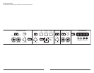
3) The input sensitivity of the two amplifiers
needs to be adjusted independently. To
properly calibrate the amplifiers for
maximum, identical, clean output, please
refer to Appendix A (page 14). After using this
procedure, you can then adjust the level of the
amplifiers by adjusting the input sensitivities
downward, if the amplifiers require attenuation
to achieve the desired system balance. If the
input sensitivities are adjusted, the amplifiers
must be recalibrated to ensure identical power
output levels.
Note:5IFiInput RangewTXJUDIPOBMMi4MBWFw
BNQMJGJFSTOFFETUPCFTFUUPiLowwFWFOJG
UIFi.BTUFSwBNQMJGJFSJTIJHIWPMUBHFBOEJUT
TXJUDIJTTFUUPiHighw"MMTJHOBMTQBTTFEPVU
of the preamp outputs of the amplifier are
DPNQBUJCMFXJUIUIFiLowwTFUUJOHPOUIFiInput
RangewDPOUSPM
4) If you would like to run a third amplifier
JOi4MBWFwDPOGJHVSBUJPOTFMFDUUIFiFull-
RangewQPTJUJPOPOUIFiOutput Modew
TXJUDIPGUIFGJSTUi4MBWFwBNQMJGJFS5IFO
connect an RCA cable from the first
i4MBWFwBNQMJGJFSTQSFBNQPVUQVUTUPUIF
TFDPOEi4MBWFwBNQMJGJFS"TZPVEJEXJUI
UIFGJSTUi4MBWFwBNQMJGJFSTFUUIFTFDPOE
i4MBWFwBNQMJGJFSTiAmp LP FilterwUPUIF
iOffwQPTJUJPO5IFODBMJCSBUFUIFUIJSE
BNQMJGJFSTiInput RangewBOEiInput
Sens.wDPOUSPMTJOUIFTBNFNBOOFSBTZPV
did for the second amplifier.
Additional amplifiers may be added to this
i.BTUFS4MBWFwDPOGJHVSBUJPOGPMMPXJOHUIFTBNF
procedure as in step 4.
Once you match the input sensitivities of
BMMUIFBNQMJGJFSTZPVDBOVTFUIFi.BTUFSw
BNQMJGJFSTiAmp LP FilterwBOEiAdvanced
Bass ControlwGFBUVSFTUPDPOUSPMUIFi4MBWFw
amplifier(s). If the remote bass control (RBC-1) is
VTFEJUOFFEPOMZCFDPOOFDUFEUPUIFi.BTUFSw
amplifier to control all the amplifiers in the
i.BTUFS4MBWFwDIBJO
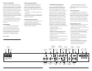
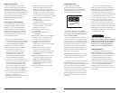
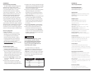
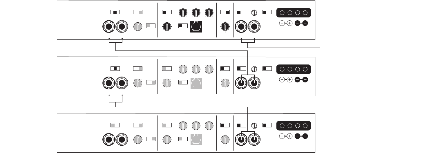
3FGFSFODFUIFEJBHSBNTIPXJOHBi.BTUFS
4MBWFwDPOGJHVSBUJPOXJUIPOFi.BTUFSwUPQ
BNQMJGJFSBOEUXPi4MBWFwBNQMJGJFST4XJUDIFT
BOEDPOUSPMTUIBUBSFEFGFBUFEJOUIFi4MBWFw
amplifiers are printed in gray.
APPENDIX D:
Master/Slave Configurations
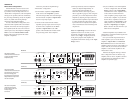
With the flexible on-board crossovers and
processing incorporated into the 1000/1v2, it
is possible to connect multiple 1000/1v2’s in a
i.BTUFS4MBWFwDPOGJHVSBUJPOXJUIFBDIBNQMJGJFS
driving its own speaker system but controlled by
the processing and filtering of only one amplifier.
This is very useful when driving multiple
subwoofers with multiple amplifiers.
To create a Master/Slave configuration, first
EFUFSNJOFXIJDIBNQMJGJFSXJMMCFUIFi.BTUFSw
amplifier and connect the main input signal to
that amplifier (from the source unit or from an
PVUCPBSEQSPDFTTPS5IJTBNQMJGJFSTiAmp LP
FilterwTFDUJPOBOEiAdvanced Bass Controlw
GFBUVSFTXJMMQSPDFTTUIFTJHOBMGPSUIFi4MBWFw
amplifier or amplifiers.
Here is the procedure for implementing a
i.BTUFS4MBWFwDPOGJHVSBUJPO
4FUUIFi.BTUFSwBNQMJGJFSTiOutput Modew
TXJUDIUPUIFDFOUFSiAmp FilterwQPTJUJPO
This will send a parallel, mono-summed signal
GSPNUIFi.BTUFSwBNQMJGJFSTiAmp LP Filterw
section to its preamp outputs.
$POOFDUBO3$"DBCMFGSPNUIFi.BTUFSw
amplifier’s preamp outputs to the main input
PGUIFGJSTUi4MBWFwBNQMJGJFS4FUUIFiSlavew
BNQMJGJFSTiAmp LP FilterwUPUIFiOffw
position. This will defeat the LP filter and the
CBTTQSPDFTTJOHPGUIJTi4MBWFwBNQMJGJFS
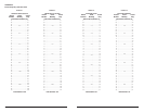
MASTER:
Preamp Output Section Infrasonic Filter “Q” Center Freq. Boost (dB) Amp LP Filter
Advanced
Bass
Control
Amplifier Input Section Subwoofer Output
MONO OUTPUT ONLY
Left Output Right Output Left Ch. Right Ch.Filter Freq. (Hz) Filter Freq. (Hz)Infrasonic Freq. (Hz) Remote Bass Port
Full Range
|
Amp Filter
|
Out Filter
Output Mode Filter Slope Mode Mode
|
Slope Input Voltage Input Sens.
Output Polarity
12dB
|
24dB
Filter Mode
LP
|
HP
Bass EQ
Off
|
On
Off
|
12dB
|
24dB Low
|
High
Normal
|
Reversed
Off
|
On
40
45
55
65
85
120
200 15
18
25
30
40
50
60 40
45
55
65
80
100
200
0.5
0.7
1.1
1.6
2.7
4.3
20
25
35
45
55
70
80 0
+4
+10
+13
+15
Preamp Output Section Infrasonic Filter “Q” Center Freq. Boost (dB) Amp LP Filter
Advanced
Bass
Control
Amplifier Input Section Subwoofer Output
MONO OUTPUT ONLY
Left Output Right Output Left Ch. Right Ch.Filter Freq. (Hz) Filter Freq. (Hz)Infrasonic Freq. (Hz) Remote Bass Port
Full Range
|
Amp Filter
|
Out Filter
Output Mode Filter Slope Mode Mode
|
Slope Input Voltage Input Sens.
Output Polarity
12dB
|
24dB
Filter Mode
LP
|
HP
Bass EQ
Off | On
Off
|
12dB
|
24dB Low
|
High
Normal
|
Reversed
Off
|
On
40
45
55
65
85
120
200 15
18
25
30
40
50
60 40
45
55
65
80
100
200
0.5
0.7
1.1
1.6
2.7
4.3
20
25
35
45
55
70
80 0
+4
+10
+13
+15
Connect Master 1000/1 Preamp Output to Slave A 1000/1 Input
Connect Slave A 1000/1 Preamp Output to Slave B 1000/1 Input
Connect Master 1000/1 Input to Signal Source
The Master amplifier’s
“Advanced Bass Control” section
is active and affects all three
amplifiers equally.
The last Slave amplifier’s
“Advanced Bass Control”
section, AMP LP Filter and
“Preamp Output”
are inactive.
This Slave amplifier’s
“Advanced Bass Control” section
and AMP LP Filter are inactive,
but the Full-Range (pass-
through) feature of its “Preamp
Output” feeds the input of the
next Slave amplifier.
SLAVE A:
SLAVE B: