


8 | JL Audio - 1000/1v2 Owner’s Manual
9
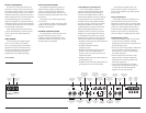
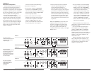
PREAMP OUTPUT SECTION
The 1000/1v2 incorporates a flexible preamp
output section, designed to make multiple
amplifier systems easy to set up.
The Preamp output can be configured in three
EJGGFSFOUiOutput Modesw
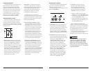
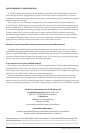
Preamp Output Section
Left Output Right Output Filter Freq. (Hz)
Full Range
|
Amp Filter
|
Out Filter
Output Mode Filter Slope
12dB
|
24dB
Filter Mode
LP
|
HP
40
45
55
65
85
12 0
200
1) “Full-Range”: This is a pass-through mode
for the preamp output, delivering the same
TJHOBMUIBUJTCFJOHGFEUPUIFi"NQMJGJFS*OQVU
4FDUJPOw*GUIFJOQVUTJHOBMJTGVMMSBOHF
the preamp output will be full-range). This
TJHOBMJTOPUBGGFDUFECZUIFiAdvanced Bass
ControlwQSPDFTTJOHTFMFDUFEGPSUIFBNQMJGJFS
2) “Amp Filter”: The preamp output delivers
the same signal that is feeding the 1000/1v2’s
amplifier section, including all the processing
JOEVDFECZUIFiAmp LP FilterwBOE
iAdvanced Bass ControlwTFDUJPOT5IJT
is primarily used for running additional
WTJOBi4MBWFwDPOGJHVSBUJPO
GSPNUIFi.BTUFSwBNQMJGJFS'PSEFUBJMFE
JOGPSNBUJPOPOi.BTUFS4MBWFwDPOGJHVSBUJPOT
TFF"QQFOEJY%QBHF*GUIFiOutput
ModewTXJUDIJTJOUIFiAmp Filterw
QPTJUJPOBOEUIFiAmp LP FilterwTXJUDI
JTJOUIFiOffwQPTJUJPOUIFSFXJMMCFOP
output from the preamp output jacks. The
JOEFQFOEFOUPVUQVUGJMUFSDPOUSPMTiFilter
SlopewiFilter FreqwBOEiFilter Modew
BSFJOBDUJWFJOiAmp FilterwNPEF
3) “Out Filter”: The preamp output is
filtered by a fully variable, active filter
incorporated into the output section
and is not affected by the bass control
processing selected for the amplifier. In
iOut FilterwNPEFUIFVTFSDBOTFMFDU
B)JHIQBTTiHPwPSMPXQBTTiLPw
GJMUFSJOHCZXBZPGUIFiFilter ModewTXJUDI
b) 12 dB/octave or 24 dB/ octave filter slope by
XBZPGUIFiFilter SlopewTXJUDI
c) A filter cutoff frequency between 40 - 200
)[GPSUIFQSFBNQPVUQVUTJHOBMCZXBZPG
UIFiFilter ControlwTXJUDI
This is completely independent of the
amplifier’s internal filter and allows the user to
match, stagger or overlap the subwoofer low-pass
filter frequency of the amplifier crossover with
the output filter’s frequency for precise control
BOEPQUJNJ[FENJECBTTQFSGPSNBODF
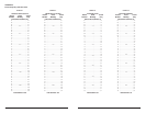
If you would like to select the filter frequency
with a higher level of precision, consult
Appendix C: Chart A-2 (page 16) of this manual.
CAUTION
!!
The signal level of the “Preamp Output” is
always low level regardless of the voltage
applied to this amplifier’s inputs and the
setting chosen on this amplifier’s “Input
Range” switch. All “Slave” amplifiers should
have their switches set to “Low”. See Appendix
D (page 18) for details.
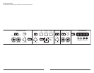
CROSSOVER CONTROLS
Crossovers are groups of individual electronic
filters which allow only certain frequency
ranges to pass through them by attenuating
frequencies outside the selected range. These
filters allow the user to specify what frequency
range will be sent out of each channel section
of the amplifier. This, in turn, allows each
speaker system to only reproduce a range of
frequencies it is well-suited for, resulting in
reduced distortion and improved fidelity.
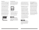
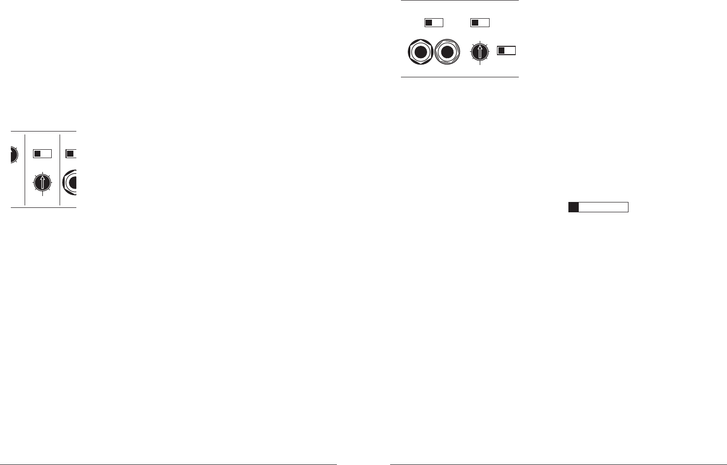
AMPLIFIER LOWPASS FILTER
The 1000/1v2 employs a sophisticated, state-
variable, low-pass active filter for its internal
channel. This feature is designed to attenuate
frequencies above its filter frequency, so that the
system’s subwoofers do not reproduce any audible
midrange content.
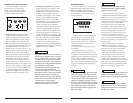
(dB)
Amp LP Filter
nced
r
ol
A
Left Filter Freq. (Hz)
Mode
|
Slope
Input V
o
Off
|
12dB
|
24dB Low
|
40
45
55
65
80
10 0
200
0
+13
+15
1) Filter Operation: The low-pass filter in the
WJTGVMMZWBSJBCMFCFUXFFO)[BOE
)[WJBUIFi'ilter Freq.wDPOUSPMLOPC
and features the ability to select between a
NPEFSBUFi12dBwQFSPDUBWFPSBTUFFQi24dBw
QFSPDUBWFTMPQFWJBUIFiMode/SlopewTXJUDI
%FQFOEJOHPOUIFTVCXPPGFSTZTUFNBOEUIF
vehicle, different slopes may be required to
produce a smooth transition to the mid-bass
speakers in the system. Experiment to find
the slope which best matches the acoustic
requirements of your system.
Tuning Hint: A trunk mounted sub whose
output has to "fight" through a rear deck or a
back seat often benefits from the 12 dB/octave
slope which lets more upper bass content
pass through. A sub that fires directly into
the listening environment is more likely
to benefit from a 24 dB/octave slope.
5IFBCPWFIJOUJTOPUiTFUJOTUPOFwy
You should always listen to the system carefully
to determine the best choice as vehicle acoustics
and other factors play a big role in choosing the
most appropriate filter slope.
2) Precise Frequency Selection: The filter
frequency markings on the front panel of
the amplifier are for reference purposes and
are generally accurate to within 1/3 octave
or better. If you would like to select the filter
frequency with a higher level of precision,
consult Appendix C: Chart A-1 (page 16)
of this manual. This chart gives you a more
accurate frequency for each of the forty
detented positions of the frequency selection
control. This method can be very useful if the
amplifier is mounted in a location where you
can’t see the front panel markings easily.
3) Defeating the Amplifier Filter: The Low-
Pass filter can also be defeated completely,
CZTXJUDIJOHUIFiMode/SlopewTXJUDIUPUIF
iOffwQPTJUJPO5IJTJTVTFGVMJGZPVBSFVTJOH
an external active crossover in the system.
Keep in mind that turning the internal
DSPTTPWFSPGGBMTPEFGFBUTUIFiAdvanced Bass
ControlwTFDUJPOQSPDFTTJOHTFFQBHFGPS
details). With the internal crossover turned
off, the 1000/1v2’s upper frequency response
MJNJUJT)[EVFUPJUTCBTTTQFDJGJD
$MBTT%EFTJHO