


5
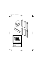
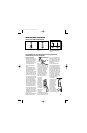
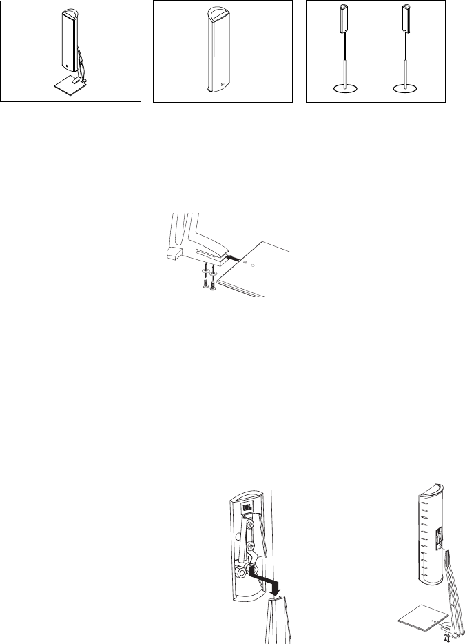
MOUNTING OPTIONS
On shelves using the optional
CVTS50 table stands.
On the wall. Wall brackets are
included.
On compatible floor stands avail-
able from other manufacturers,
using the supplied floor stand
adaptors.
SATELLITES AND SURROUNDS
Important Safety Notes:
•
The table stand consists of
two main parts: a metal col-
umn and a glass base. Be
extremely careful in han-
dling the fragile glass base
to avoid breakage that
might result in personal
injury.
•
The CVTS50 table stands
are only intended for use
with the CVSAT50 speaker.
Attempting to use the
stands with any other model
speaker is unsafe and may
result in personal injury and
damage to the equipment.
•
The stands must be placed
in a safe location, protected
from young children and
pets who might topple the
stands, possibly resulting in
serious injury. Never place
the stand so that any part of
it is sticking out over the
edge of the table, shelf or
other surface underneath it.
•
Do not install the CVSAT50
or any other speaker on the
table stand in a horizontal
orientation, as this would be
unstable and might result in
personal injury.
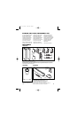
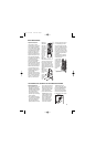
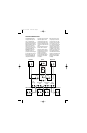
Carefully insert the glass base
into the slot in the column,
lining up
the holes in the base with the
holes in the bottom of the col-
umn. Screw in the bolts, mak-
ing sure the plastic washers
are between the bottom of
the glass base and the bolt
heads. Tighten the bolts
securely using a Philips
screwdriver (not supplied).
Do not overtighten, as this
might strip the threads,
which is not covered by
the warranty.
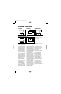
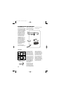
Prepare the
speaker wire
as described
on page 8.
Remove the
rubber strip
from the back
of the column,
revealing the
wire-manage-
ment channel.
Thread the
two conduc-
tors through the hole at the
top of the channel. Make sure
to preserve the proper polar-
ity (+ and – connections) by
placing the positive conduc-
tor on the left, and the nega-
tive conductor on the right,
looking at the front of the
stand column.
Use the supplied terminal
wrench to loosen the red col-
lar of the binding post until
the pass-through hole under-
neath it is revealed. Insert the
bare end of the positive wire
through the hole, then screw
the collar down until it is tight.
Follow the same procedure
to connect the negative wire
to its terminal. Slowly lower
the mounting bracket on the
satellite onto the top
of the metal col-
umn of the CVTS50
stand. Gently pull
the slack out of the
wire. Carefully
press the rubber
strip in place over
the wire-manage-
ment channel,
being careful to
keep the speaker
wire in the channel
and to avoid pinch-
ing it with the rubber strip.
ATTACHING THE CVTS50 TABLE STAND (AVAILABLE
SEPARATELY) TO THE CVSAT50
CV OM 6/15/04 4:06 PM Page 5