


9
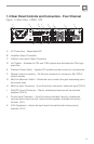
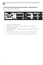
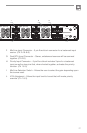
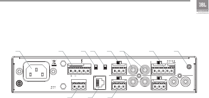
1.3 Rear Panel Controls and Connectors - Four Channel
A. AC Power Inlet – Detachable IEC
B. Amplifier Output Connector
C. Auxiliary Line Level Output Connector
D. Hi-Z Switch – Enables the 70V and 100V outputs and activates the 70Hz high
pass filter
E. Phantom Power Switch – Applies 27V phantom power source for microphones.
F. Remote volume connector – RJ-45 style connector to connect to JBL CSR-V
control module
G. Mic/Line Selection Switch – Allows the user to select the gain depending upon
the source used
H. Mic/Line Input Connector – 3 pin Euro-block connector, balanced input (Ch2-4)
I. Dual RCA Input Connector – Stereo, unbalanced sources will be summed
together (Ch2-4)
J. Priority Input Connector – 5 pin Euro-block includes 3 pins for a balanced
input as well as two pins that, when shorted together, activates the priority
function. (Ch1)
K. VOX Adjustment – allows the input level to be set that will invoke priority
override. (CH1)
Figure 1.3 Rear View - CSMA 1120
AUX OUT
CSR-V ONLY
Hi-Z PHANTOM
CH3 INPUT
CH4 INPUT
CH2 INPUT
CH1 INPUT
100V 70.7V COM
MICLINE
MICLINE
MICLINE
MICLINE
MONO SUM MONO SUM
VOX
MONO SUM
100-240 V~ 50/60Hz 40W
CSMA 1120
MADE IN MALAYSIA
CAUTION - TO REDUCE THE RISK
OF ELECTRIC SHOCK, GROUNDING
OF THE CENTER PIN OF THE PLUG
MUST BE MAINTAINED.
5028384
AMP OUT
CLASS 2
WIRING
CH2-4 IN / AUX OUT
PRIORITY
A B D E G J KI
C F H