10
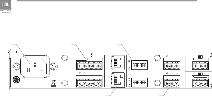
1.4 Rear Panel Controls and Connectors - Eight Channel
Figure 1.4 Rear View - CSMA 2120
5025056
100-240 V~ 50/60Hz 60W
CSMA 2120
CSR-V
21 3 4 5 6
7
8 9 10 11 12
MIC
MONO SUM
MONO SUM MONO SUM
AMP 1AMP 2
AMP 1
AUX 1 OUT
CH4 INPUT
INPUT ROUTING
AUX 2 OUT
AMP 2
LINE
100V 70.7V COM
CH8 INPUT
CH3 INPUTCH7 INPUT
CH2 INPUTCH6 INPUT
CH1 INPUTCH5 INPUT
PRIORITY
PRIORITY
MADE IN MALAYSIA
MICLINE
MICLINE
MICLINE
MICLINE
MICLINE
MICLINE
MICLINE
CAUTION - TO REDUCE THE RISK OF
ELECTRIC SHOCK, GROUNDING OF THE
CENTER PIN OF THE PLUG MUST BE
MAINTAINED.
1 - CH1 TO AMP2
2 - CH2 TO AMP2
3 - CH3 TO AMP2
4 - CH4 TO AMP2
5 - AMP1 Hi-Z
6 - PHANTOM
7 - CH5 TO AMP1
8 - CH6 TO AMP1
9 - CH7 TO AMP1
10 - CH8 TO AMP1
11 - AMP2 Hi-Z
12 - NC
CH 1 VOX
CH 5 VOX
MONO SUM
MONO SUM
MONO SUM
OUTPUTS
CLASS 2
WIRING
I HG
A B D
C E
F J
A. AC Power Inlet – Detachable IEC
B. Amplifier Output Connector – Outputs available for low impedance or
constant voltage systems.
C. Remote Volume Control – RJ45 style connector to connect to a JBL CSR-V
control module.
D. Dip switches for input routing, phantom power, and 70/100V operation
E. Aux Out – Auxiliary line level output connector for each output channel.


