


19
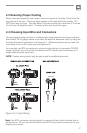
2.6 Wiring Your Audio System
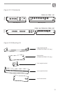
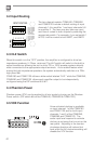
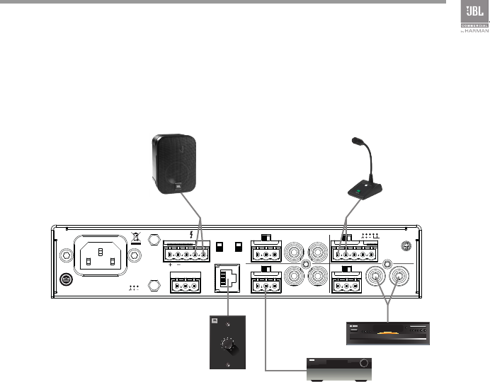
Typical input and output wirings are shown in Figure 2.6.
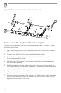
INPUTS: Connect input wiring for both channels using either the RCA or the
Euroblock input for each channel.
OUTPUTS: You may use either low impedance or high impedance speakers.
Always be sure to maintain the proper polarity when wiring speakers.
Low Impedance Speakers should be driven using the +/- pins of the amplifier output
connector. The minimum impedance an amplifier channel can drive is 4 Ohms.
Therefore, you can connect up to four 16 Ohm speakers, two 8 Ohm speakers or one
4 Ohm speaker to an amplifier output channel.
High Impedance Speakers should be driven using the appropriate (70V or 100V) pin
to speaker (+) and the COM pin to speaker (-) of the amplifier output connector. The
minimum impedance that can be driven from each output is provided in Appendix
A. Note that the HI-Z switch must be ON in order to provide audio to the high
impedance outputs.
WARNING: Do not connect to both low impedance speakers and high impedance
speakers from the same audio output channel.
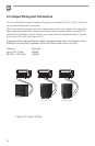
Figure 2.6 Wiring Audio System
Professional audio system
AUX OUT
CSR-V ONLY
Hi-Z PHANTOM
CH3 INPUT
CH4 INPUT
CH2 INPUT
CH1 INPUT
100V 70.7V COM
MICLINE
MICLINE
MICLINE
MICLINE
MONO SUM MONO SUM
VOX
MONO SUM
100-240 V~ 50/60Hz 40W
CSMA 1120
MADE IN MALAYSIA
CAUTION - TO REDUCE THE RISK
OF ELECTRIC SHOCK, GROUNDING
OF THE CENTER PIN OF THE PLUG
MUST BE MAINTAINED.
5028384
AMP OUT
CLASS 2
WIRING
CH2-4 IN / AUX OUT
PRIORITY
CD /OPTICAL
SPK 1 + 2 VIRTUAL
LEVEL
CSR-V