


22
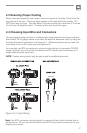
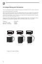
3.2 Input Routing
The two channel models, CSMA240, CSMA280
and CSMA2120 include a default routing of input
channels 1-4 to amplifier 1 and input channels 5-8
to amplifier 2. The user may also take any input
and have it routed to both outputs by selecting the
appropriate switch. For example, if you set switch 1
to ON, it will be routed to both AMP1, and AMP2.
3.3 Hi-Z Switch
When this switch is in the “OFF” position, the amplifier is configured to drive low
impedance speakers, (4 Ohms ,minimum) The Hi-Z switch will switch in the built-in
output transformer allowing the unit to drive 70V or 100V speaker systems directly
when connected to the appropriate output terminals. As an added feature when
driving the high impedance speakers, the system automatically switches in a 70Hz
high pass filter.
CSMA180 and CSMA1120 utilizes a slide switch labeled “HI-Z.” while the CSMA240,
CSMA280 and CSMA2120 allows each amplifier output to be independently
configured using the DIP switches #5 & #11.
3.4 Phantom Power
Phantom power (27V) can be applied to all mic inputs by turning on the Phantom
Power switch. (DIP switch #6 on the CSMA240, CSMA280 & CSMA2120.)
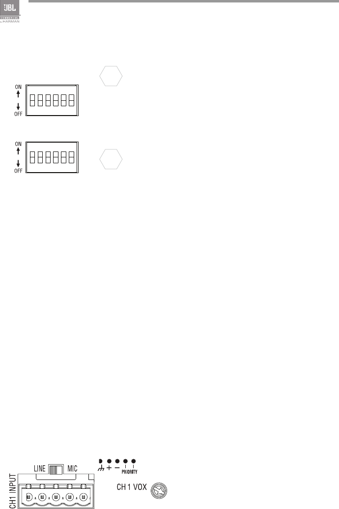
3.5 VOX Function
Voice activated ducking is available
on input channel 1 of the CSMA180
and CSMA1120 and for both input
channels 1 and 5 of the CSMA240,
CSMA280 and CSMA2120. The
audio input level required to activate
ducking is set using the trim pot on the
rear panel. Adjusting in the counter-
clockwise direction will reduce that
level while the full clockwise setting will
disable the VOX function.
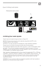
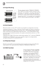
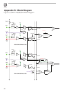
213456
7
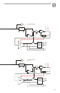
8910 11 12
INPUT ROUTING
1 - CH1 TO AMP2
2 - CH2 TO AMP2
3 - CH3 TO AMP2
4 - CH4 TO AMP2
5 - AMP1 Hi-Z
6 - PHANTOM
7 - CH5 TO AMP1
8 - CH6 TO AMP1
9 - CH7 TO AMP1
10 - CH8 TO AMP1
11 - AMP2 Hi-Z
12 - NC