


5
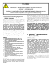
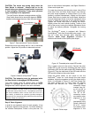
CAUTION: The mount may swing freely when the
Gear Switch is released. Always hold on to the
mount before you release the gear switch to prevent
it from swinging. Otherwise it may cause personal
injury or damage to the equipment.
Turn the Tension Adjuster counterclockwise until the
Gear Switch Knob can be turned 90 degree to OPEN
position to disengage the worm from the worm wheel.
Figure 7. Gear switch and Tension Adjuster
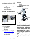
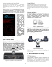
Rotate the mount head along the R.A. axis to horizontal
position. Adjust the CW position to balance the mount.
Figure 8. Balance a SkyGuider
TM
mount
CAUTION: The balancing must be performed while
the Gear Switch is disengaged (OPEN position).
Turn Gear Switch Knob 90 degree again to LOCK
position to re-engage the worm to the worm wheel.
Retighten the Tension Adjuster a few turns clockwise.
The rule of thumb is to fully screw in the Tension Adjuster
andthenbackoutbyabout2turns.Theoptimumspotvaries
with actual conditions which can be from half a turn to 2
turns.Ideally,it shouldbeata positionjustdeepenoughto
eliminateanyfreemovement(play)whileforceontheworm
assemblyiskeptataminimum.
.
Step 6. Polar Alignment
In order for an equatorial mount to track properly, it has
to be polar aligned to the pole star. For those located in
the northern hemisphere, Polaris is the pole star. For
those in the southern hemisphere, use Sigma Octantis in
Octans as the pole star.
To locate the pole star from the polar scope, take off the
Polar Axis Cover and Polar Scope Cover. Look through
the polar scope eyepiece to locate Polaris (if you are
located in northern hemisphere). Slightly turn the tripod
Center Rod Knob to loosen the mount head. Adjust the
Azimuth Adjustment Knobs to do a fine adjustment of the
mount to center the pole star in the azimuth direction.
Tighten the Center Rod Knob to secure the mount.
Slightly loosen the two Latitude Locking T-bolts on the
side of the mount, turning the Latitude Adjustment Knob
to adjust the latitude (altitude). Re-tighten the locking
screws.
The SkyGuider
TM
mount is equipped with iOptron’s
AccuAligning
TM
dark field illuminated polar scope. You
can do a fast and accurate polar alignment with
iOptron’s Quick Polar Alignment procedure to
maximize the benefit of the iOptron polar scope.
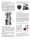
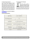
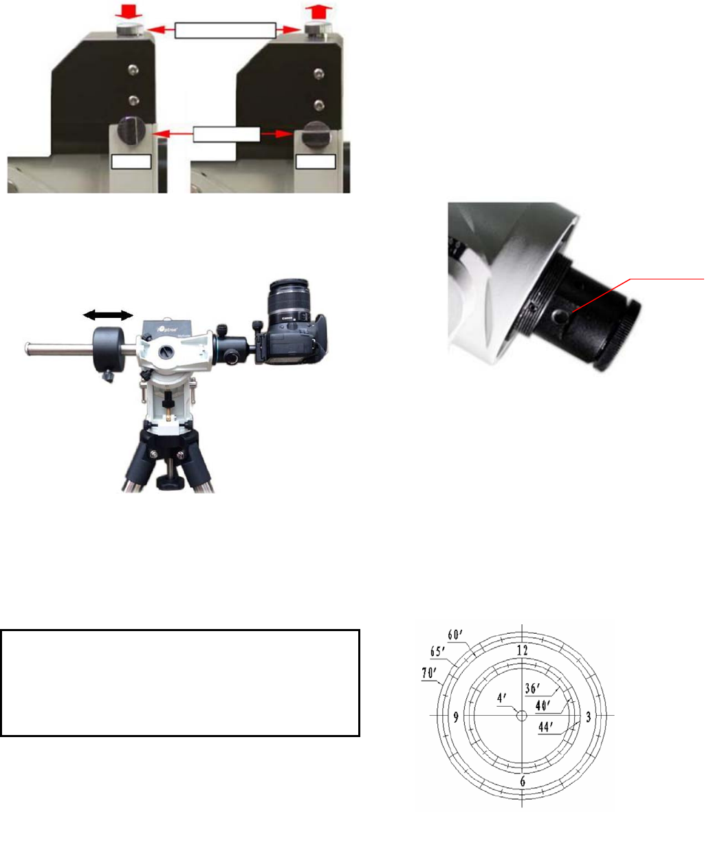
Plug a power source to the mount. Connect the polar
scope LED to the mount by threading the polar scope
illuminating LED into the polar scope LED threading hole
(Figure 9). Plug the other end of the LED cable into the
LED socket located on the control board.
Press the power switch on the mount to turn the
SkyGuider
TM
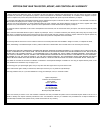
mount on. Look through the polar scope
eyepiece. Adjust the eyepiece to bring the reticle dial in
focus. As indicated in Figure 10, the Polar Scope Dial
has been divided into 12 hours along the angular
direction with half-hour tics. There are 2 groups, 6
concentric circles
marked from 36’
to 44’ and 60’ to
70’, respectively.
The 36’ to 44’
concentric circles
are used for polar
alignment in the
northern
hemisphere using
Polaris. While the
60’ to 70’ circles
are used for polar
alignment in the
TensionAdjuster
GearSw itch
LOCK
OPEN
Figure 10. Threaded polar scope LED socket
LEDthread
Figure 9. Polar scope