


4
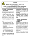
STEP 1. Select Mount Latitude Range
Carefully remove the mount from the package and
familiarize yourself with the components shown in Error!
Reference source not found..
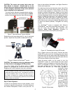
The mount is by default shipped with the Long Latitude
Adjustment Knob installed (for 35-60º). At lower
latitudes of 0-35º, the Short Latitude Adj. Knob needs to
be used. To change this knob, remove the Latitude
Locking T-bolts on both sides (Be careful not to lose the
washers). Unscrew Bottom Post Locking Screw to free
the Bottom Latitude Adj. Post and remove the Latitude
Adj. Knob. Thread in evenly
the Short Latitude Adj. Knob
to Top and Bottom Latitude Adjustment Posts. Reinstall
and tighten bottom locking screw. Lastly, with 4 washers
all properly placed, insert and tighten the Latitude Locking
T-bolts into the upper threaded holes.
(b)
Figure 4. Switching latitude adjustment knobs
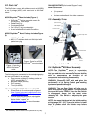
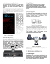
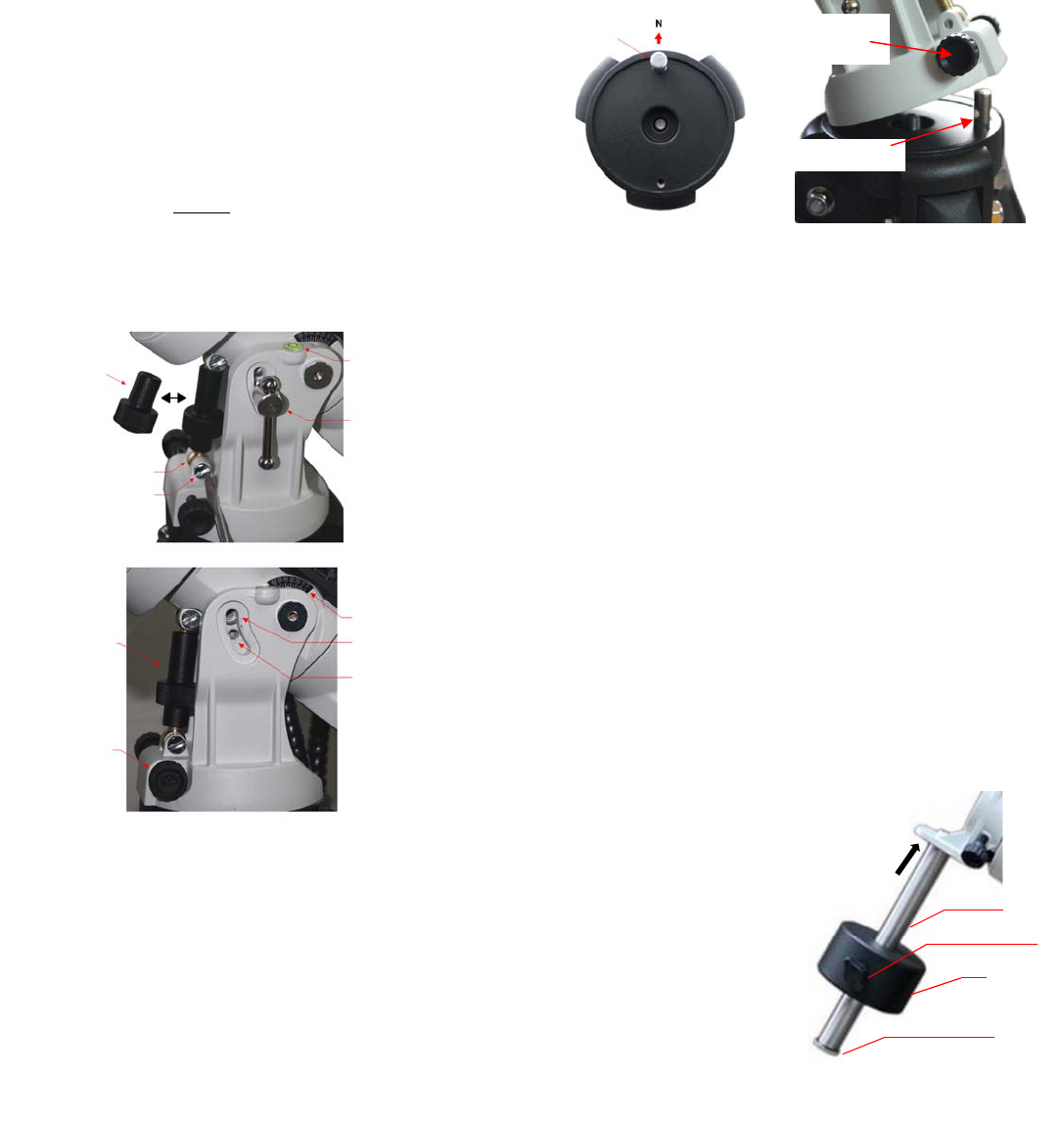
STEP 2. Setup Tripod and Mount
Expand the tripod legs and adjust the tripod height.
Position the tripod so that the Alignment Peg faces north,
(if you are located in the northern hemisphere). If you
are located in southern half—face the Alignment Peg
south. Thread the Tripod Center Rod into the tripod head.
Install the Tripod Support Tray and thread the Tray
Locking Knob onto it. Do not fully tighten the Tray
Locking Knob.
There are two threaded holes on the tripod head for
alignment peg installation. You may place the peg at
either position, as long as the mount does not hit the
tripod leg when tracking.
Retract both Azimuth Adj. Knobs to allow enough
clearance inside the chamber. Position the mount on the
tripod head with the Alignment Peg in between the 2
Azimuth Adj. Knobs. Thread the Center Rod into mount
to secure it with tripod. Tighten the Tray Locking Knob to
fully spread the tripod legs. Adjust the tripod legs to
level the mount using the Level Bubble.
Figure 5. Set up tripod and mount
STEP 3. Adjust Latitude
This step requires you to know the latitude of your
current location. This can be found on the Internet, with
a GPS navigator or a GPS capable cell phone. You will
have to change this latitude setting every time you
significantly change your night sky viewing location. This
setting directly affects the mount’s tracking accuracy.
Slightly loosen the Latitude Locking T-bolts. Turn
Latitude Adjust Knob to adjust the latitude until the arrow
points to your current latitude on the Latitude Indicator
(see Figure 4b). Relock the Latitude Locking T-bolts. At
this point, with the mount leveled and pointed north, and
the latitude set, the Polar Axis (R.A. axis) should be
pointing very close to the NCP and Polaris. This
alignment accuracy will be sufficient for visual tracking
and short duration astrophotography.
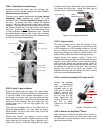
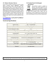
STEP 4. Install Counterweight (CW) shaft and CW
Thread the stainless
steel counterweight
shaft onto the 3/8”-16
threaded hole on the
short arm of the DEC
Adapter. Remove CW
Safety Screw and slide
the CW onto the CW
shaft. Tighten the CW
Locking Screw to hold
the CW in place.
Tighten the CW Safety
Screw.
STEP 5. Balance the SkyGuider
TM
Mount
After attaching an optional ball head and a camera or
telescope onto the mount, the SkyTracker mount must
be balanced to ensure minimum stress on the mount
gears and motors inside.
Short Lat. Adj. Knob
Locking Screw
Bottom Lat. Adj. Post
Level Bubble
Lat. Locking T-bolt
Long Lat. Adj. Knob
Azi. Adj. Knob
Latitude Indicator
For Low Latitude
For High Latitude
Alignment Peg
Azimuth
Adjustment Knob
Alignment Peg
Figure 6. CW shaft and CW
CWshaft
CW
CWsafetyscrew
CWlockingscrew