5
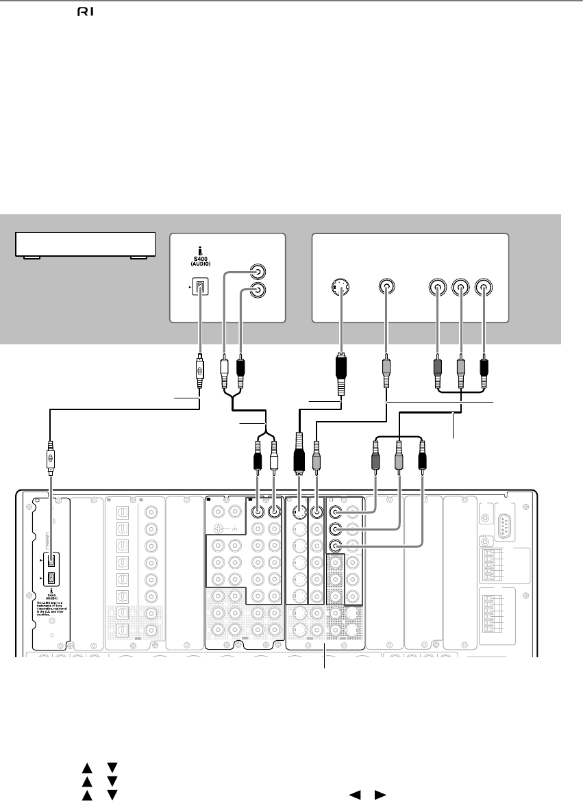
Connecting to DVD player with i.LINK terminal
Disconnect the cable when this type of connection is made on an IntegraRESEARCH/Onkyo DVD player.
1. Use the S400 4-pin i.LINK cable to connect the i.LINK (AUDIO) terminal on the RDC-7.1 to the i.LINK
(AUDIO) terminal on the i.LINK (AUDIO)-enabled DVD player.
2. (Recommended) Use an audio connection cable to connect the RDC-7.1
’
s AUDIO IN 4 L/R to the analog
audio output on your DVD player.
3. Follow one of the instructions shown below to make a connection for video input.
(An appropriate option board [H] [I] should be installed to connect a DVD player.)
1. Use a component video connection cable to connect the RDC-7.1’s COMPONENT VIDEO IN 1 to the Compo-
nent Video Output on your DVD player. Note that TV or projector must also be connected via COMPONENT
terminal.
2. Use a S video connection cable to connect the RDC-7.1’s S VIDEO IN 1 to the S Video Output on your DVD
player.
3. Use a composite video connection cable to connect the RDC-7.1’s VIDEO IN 1 to the video output on your
DVD player.
4. When the connection is completed, power on the RDC-7.1 and TV (See steps 1 to 5 on page 7).
5. Assign the DVD input source.
(Remote controller)
1. Press the [Input] button, and then roll the scroll wheel to select “DVD.”
2. Press the scroll wheel, and then press the [Setup] button.
3. Use the [ ]/[ ] buttons to select “Input Setup,” and then press the [Enter] button.
4. Use the [ ]/[ ] buttons to select “Audio Assign” and then press the [Enter] button.
5. Use the [ ]/[ ] buttons to select “i.LINK,” and then use the [ ]/[ ] buttons to select the DVD player.
6. After setting, press the [Setup] button.
B
“Net
-
Tune”
is
a
trademark
of
Onkyo
Corporation.
ETHERNET
(
Net
-
Tune
)
B
(
ASSIGNABLE
)
(
ASSIGNABLE
)
K
L
22
11
66
55
44
33
22
11
C D
DIGITAL IN DIGITAL IN
OPTICAL COAXIAL
OUT
SBR SBL
SR SL
SUB C
FR FL
SBR SBL
SR SL
SUB C
FR
FL
E
MULTI
-
CH
IN
1
MULTI
-
CH
IN
2
AUDIO IN
1
3
2
1
PH
2
3
9
8
7
6
5
4
4
5
LRRL
GND
OUT
LR
LR
R L
F
G
L
IN
1
IN
2
OUT
HDMI
S
VIDEO VIDEO
IN IN
IN
1
IN
2
3
2
1
Y
P
B
PR
COMPONENT
VIDEO
IN
3
IH
6
5
4
Y
P
B
PR
2
1
4
3
S VIDEOS VIDEO VIDEOVIDEO
OUT OUT
OUT
1
J
OUT
(
HD/ BNC
)
Y
P
B
P
R
Y
P
B
P
R
COMPONENT VIDEO
IN
(
HD/ BNC
)
K
ANTENNA
FM
75
AM
AC
INLET
(
SINGLE
)
A
UDD
RS
232
IR
IN
+
12
V DC PWR SUPPLY
MAIN
GND
ZONE
3
ZONE
2
GND
C
D
E
B
A
12
V
TRIGGER
OUT
100mA MAX.
100mA MAX.
100mA MAX.
TOTAL
100mA MAX.
200mA MAX.
20mA MAX.
12 V
TRIGGER
OUT
E
A
Y
P
B
PR
COMPONENT
OUT (RCA)
R
L
VIDEO
OUT
ANALOG
S VIDEO
OUT
AUDIO OUT
3-2.
S video
connection
cable
2. Audio
connection
cable
1. i.LINK cable
RDC-7.1
DVD player
3-1.
Component
video
connection
cable
3-3.
Video
connection
cable
Option


