


3
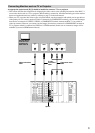
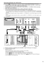
An appropriate option board [H] [I] should be installed to connect a TV or a projector.
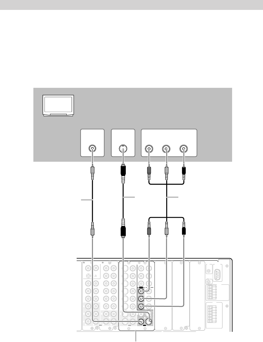
• This section describes the connections for displaying the video source or the operating information of the RDC-7.1
on a monitor device such as a TV or projector. Before making a connection, check the terminal types on the monitor
device and acquire the necessary cables by referring to page 31 in the main manual.
• When your TV or monitor has various types of input terminals, use the connection with which you can get the best
video quality. On TV screen or projector which is connected via COMPONENT terminal, you can view the images
from devices connected via VIDEO, S-VIDEO or COMPONENT terminal, because the RDC-7.1 has a built-in
video-up converter. However, you cannot view the images from devices connected via COMPONENT terminal on
TV or projector which is connected via VIDEO or S-VIDEO terminal (In this case of connection, images will be
available if you use an HDMI terminal board).
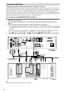
Connecting Monitors such as TV or Projector
K
L
S
BL
SL
C
S
BL
SL
C
MULTI
-
CH
IN
1
MULTI
-
CH
IN
2
AUDIO IN
1
3
2
1
PH
2
3
9
8
7
6
5
4
4
5
LRRL
GND
OUT
LR
LR
R L
F
G
L
IN
1
IN
2
OUT
HDMI
S
VIDEO VIDEO
IN IN
IN
1
IN
2
3
2
1
Y
PB
PR
COMPONENT
VIDEO
IN
3
IH
6
5
4
Y
P
B
PR
2
1
4
3
S VIDEOS VIDEO VIDEOVIDEO
OUT OUT
OUT
1
J
OUT
(
HD/ BNC
)
Y
P
B
P
R
Y
P
B
P
R
COMPONENT VIDEO
IN
(
HD/ BNC
)
K
ANTENNA
FM
75
AM
AC INLET
UDD
RS
232
IR
IN
+
12
V DC PWR SUPPLY
MAIN
GND
ZONE
3
ZONE
2
GND
C
D
E
B
A
12
V
TRIGGER
OUT
100mA MAX.
100mA MAX.
100mA MAX.
TOTAL
100mA MAX.
200mA MAX.
20mA MAX.
12 V
TRIGGER
OUT
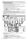
E
VIDEO
IN
S VIDEO
IN
Y
P
B
PR
COMPONENT
VIDEO (RCA)
IN
Monitor device
such as TV or
projector for
Main room A
Video connection
cable
Component video
cable
S video
connection
cable
Option