


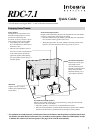
4
An appropriate option board [H] [I] should be installed to connect a DVD player.
The description here guides you to make connection between the RDC-7.1 and your DVD player in a quickest way
where no modification is required for the default settings of the unit. The guidance is divided into 4 ways depending on
the type of DVD player: If you have an IntegraRESEARCH RDV-1.1, follow the steps in this page for the typical
connection procedure. If you plan to connect your DVD player, including the RDV-1.1, via the i.LINK terminal, refer
to page 5. If you have a universal DVD player without i.LINK terminals to connect, refer to page 6. Finally, if you have
any other DVD player than shown above, go to page 33 in the main manual.
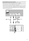
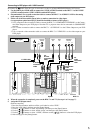
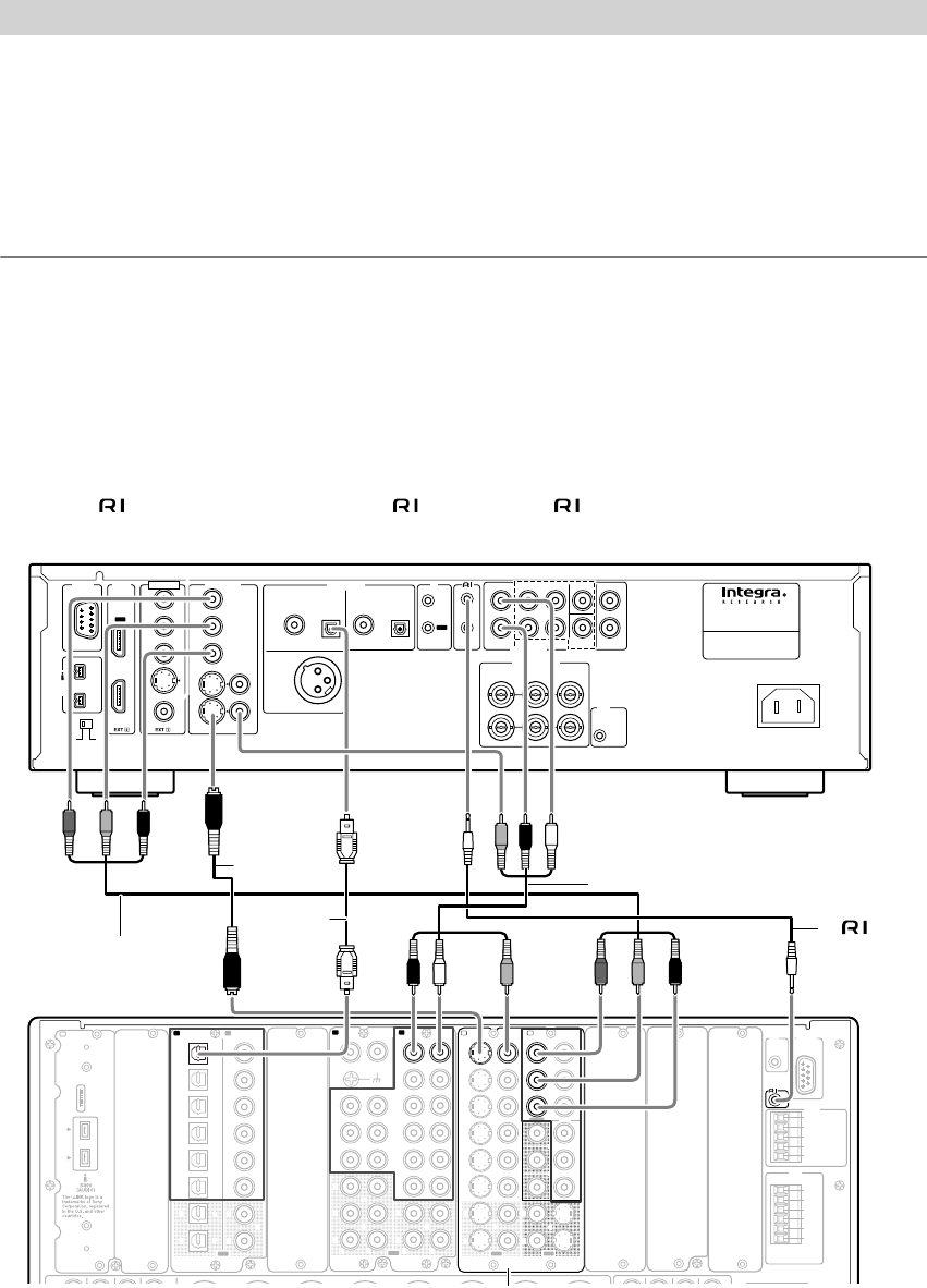
Connecting to an IntegraRESEARCH DVD player RDV-1.1
1. Use an optical cable to connect the RDC-7.1’s DIGITAL IN OPTICAL 1 to the AUDIO OUT DIGITAL 1
OPTICAL on your RDV-1.1.
2. Use an AV cable to connect the RDC-7.1’s AUDIO IN 4 L/R to the AUDIO OUT D. MIX L/R on your
RDV-1.1.
3. Follow one of the instructions shown below to make a connection for video input.
1. Use a component video connection cable to connect the RDC-7.1’s COMPONENT VIDEO IN 1 to the VIDEO
OUT COMPONENT on your RDV-1.1. Note that TV or projector must also be connected via COMPONENT
terminal.
2. Use a S video cable to connect the RDC-7.1’s S VIDEO IN 1 to the VIDEO OUT S VIDEO on your RDV-1.1.
3. Use an AV cable to connect the RDC-7.1’s VIDEO IN 1 to the video output on your RDV-1.1.
4. Use an cable to connect the RDC-7.1’s terminal to the REMOTE CONTROL on your RDV-1.1.
Note:
If your AV Controller has i.LINK terminals, see page 5.
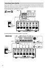
Connecting a DVD Player
COAXIAL OPTICAL OPTICALCOAXIAL
DIGITAL
1
DIGITAL
2
DIGITAL 2
(
BALANCED
)
AES/EBU
AUDIO
OUT
MODEL NO.
RDV
-
1.1
DVD
PLAYER
AC INLET
D. MIX FRONT SURR
1
CENTER SURR
2
L
R
L
R
IN
SUB
WOOFER
1
2
YPB PR
OUT
OUT
IN
REMOTE
CONTROL
VIDEO
OUT
COMPONENT
VIDEO
S
VIDEO VIDEO
S
VIDEO
Y
P
B
PR
Y
P
B
PR
IN
1
+
21
RS
232
HDMI
VIDEO
IN
IR
S400
(
AUDIO
)
AUDIO
OUT
HD VIDEO
OUT
COMPONENT
12
V
TRIGGER
SURR
MODE
(
AUDIO OUT
)
(
ASSIGNABLE
)
(
ASSIGNABLE
)
K
L
“Net
-
Tune”
is
a
trademark
of
Onkyo
Corporation.
ETHERNET
(
Net
-
Tune
)
22
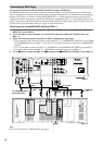
11
66
55
44
33
22
1 1
C D
DIGITAL IN DIGITAL IN
OPTICAL COAXIAL
OUT
SBR SBL
SR SL
SUB C
FR FL
SBR SBL
SR SL
SUB C
FR
FL
E
MULTI
-
CH
IN
1
MULTI
-
CH
IN
2
AUDIO IN
1
3
2
1
PH
2
3
9
8
7
6
5
4
4
5
LRRL
GND
OUT
LR
LR
R L
F
G
L
IN
1
IN
2
OUT
HDMI
S
VIDEO VIDEO
IN IN
IN
1
IN
2
3
2
1
Y
PB
PR
COMPONENT
VIDEO
IN
3
IH
6
5
4
Y
P
B
PR
2
1
4
3
S VIDEOS VIDEO VIDEOVIDEO
OUT OUT
OUT
1
J
OUT
(
HD/ BNC
)
Y
P
B
P
R
Y
P
B
P
R
COMPONENT VIDEO
IN
(
HD/ BNC
)
K
ANTENNA
FM
75
AM
AC
INLET
(
SINGLE
)
A B
UDD
RS
232
IR
IN
+
12
V DC PWR SUPPLY
MAIN
GND
ZONE
3
ZONE
2
GND
C
D
E
B
A
12
V
TRIGGER
OUT
100mA MAX.
100mA MAX.
100mA MAX.
TOTAL
100mA MAX.
200mA MAX.
20mA MAX.
12 V
TRIGGER
OUT
E
A B
RDV-1.1
1. Optical
cable
4. cable
2. AV cable
3-1. Component video
connection cable
RDC-7.1
3-2. S video
cable
3-3. AV
cable
Option